(No.MA148)1-9
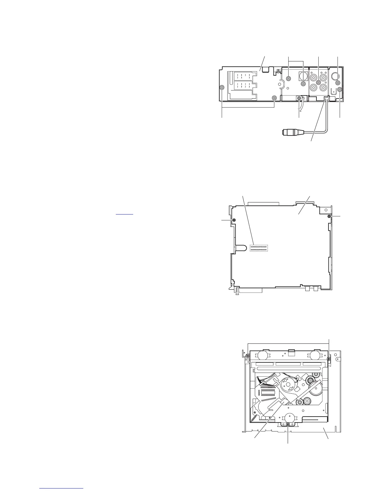
3.1.5 Removing the rear bracket
(See Fig.6)
• Prior to performing the following procedure, remove the bottom
cover.
(1) Remove the four screws E, three screws F and three
screws G attaching the rear bracket on the back side of the
main body.
(2) Remove the screw E' attaching the rear bracket on the
back side of the main body. (For KD-G611 model only)
(3) Take out the rear bracket.
Reference:
When attaching the rear bracket to the main body, insert the
steering remote into the slot of the rear bracket.
Fig.6
3.1.6 Removing the main board
(See Fig.7)
• Prior to performing the following procedure, remove the front
panel assembly, front chassis assembly, side panel, bottom
cover and rear bracket.
(1) Remove the two screws H attaching the main board.
(2) Disconnect the connector CN501
and take out the main
board.
Fig.7
3.1.7 Removing the CD mechanism assembly
(See Fig.8)
• Prior to performing the following procedure, remove the front
panel assembly, front chassis assembly, side panel, bottom
cover, rear bracket and main board.
(1) Remove the three screws J attaching the top chassis.
(2) Take out the CD mechanism assembly.
Fig.8
EE'E
Rear bracket
GFG
Insert the subwoofer
output into the slot.
Main board
H
H
CN501
J
J
CD mechanism assembly
Top chassis
 Loading...