1-8
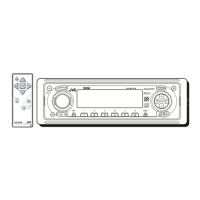
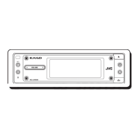
KD-LH7R
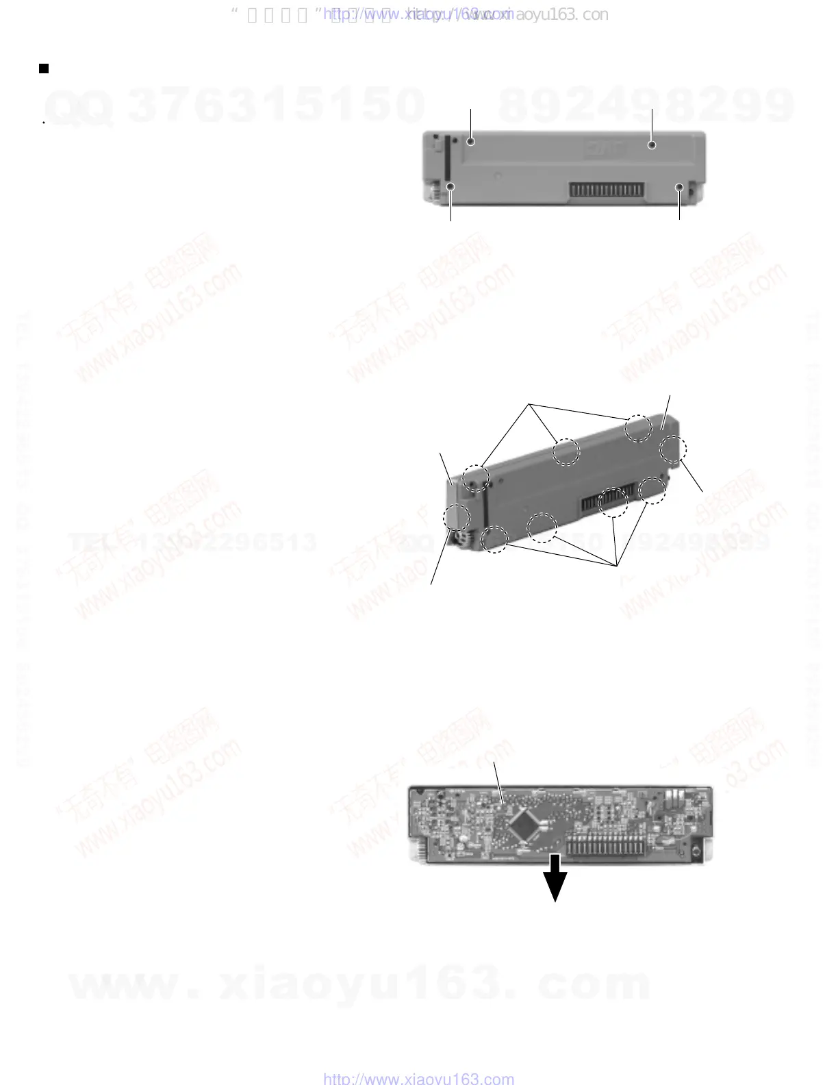
Removing the (LCD & key) control switch
board (See Fig.11
~ 13)
Prior to performing the following procedure, remove
the front panel assembly.
Remove the four screws I attaching the rear cover
on the back of the front panel assembly.
Unjoint the nine joints i with the front panel and the
rear cover.
Remove the control switch board on the back of the
front panel.
1.
2.
3.
I
I
I
I
Fig. 11
Fig. 13
Fig. 12
LCD & Key control board
Joint i
Joint i
Joint i
Joint i
Front panel
Rear cover
w
w
w
.
x
i
a
o
y
u
1
6
3
.
c
o
m
Q
Q
3
7
6
3
1
5
1
5
0
9
9
2
8
9
4
2
9
8
T
E
L
1
3
9
4
2
2
9
6
5
1
3
9
9
2
8
9
4
2
9
8
0
5
1
5
1
3
6
7
3
Q
Q
TEL 13942296513 QQ 376315150 892498299
TEL 13942296513 QQ 376315150 892498299
http://www.xiaoyu163.com
http://www.xiaoyu163.com
“无奇不有”电路图网 http://www.xiaoyu163.com
 Loading...