(No.MA194)1-7
SECTION 4
ADJUSTMENT
4.1 KS-AX5500 IDOLING CURRENT ADJUSTMENT
The potential display becomes positive or negative depending on selected one TP.
Adjust the voltage regardless of the potential.
Make the value of each VR equal.
Instrument requited
DC power
Multimeter
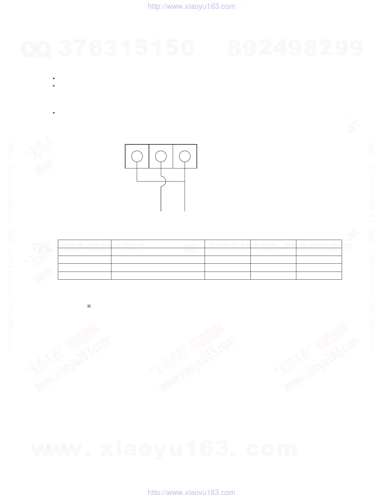
Connection
Connect the DC power to the body (+B, remote and GND). After three minutes or more, start measurement
(wait until the voltage is stabilized).
Remote GND +B
DC power GND DC power +B
Short-circuit the remote terminal and +B terminal.
Use the thick cord for connection.
Adjustment
Adjustment VR
VR101
VR201
VR301
VR401
Adjusted value
1.5mV
1.5mV
1.5mV
1.5mV
MIN
1.0mV
1.0mV
1.0mV
1.0mV
MAX
2.0mV
2.0mV
2.0mV
2.0mV
TP
TP105orTP106-TP107(GND)
TP205orTP206-TP207(GND)
TP305orTP306-TP307(GND)
TP405orTP406-TP407(GND)
w
w
w
.
x
i
a
o
y
u
1
6
3
.
c
o
m
Q
Q
3
7
6
3
1
5
1
5
0
9
9
2
8
9
4
2
9
8
T
E
L
1
3
9
4
2
2
9
6
5
1
3
9
9
2
8
9
4
2
9
8
0
5
1
5
1
3
6
7
3
Q
Q
TEL 13942296513 QQ 376315150 892498299
TEL 13942296513 QQ 376315150 892498299
http://www.xiaoyu163.com
http://www.xiaoyu163.com

 Loading...