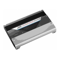
KS-AX6700
1-6
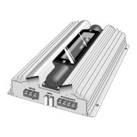
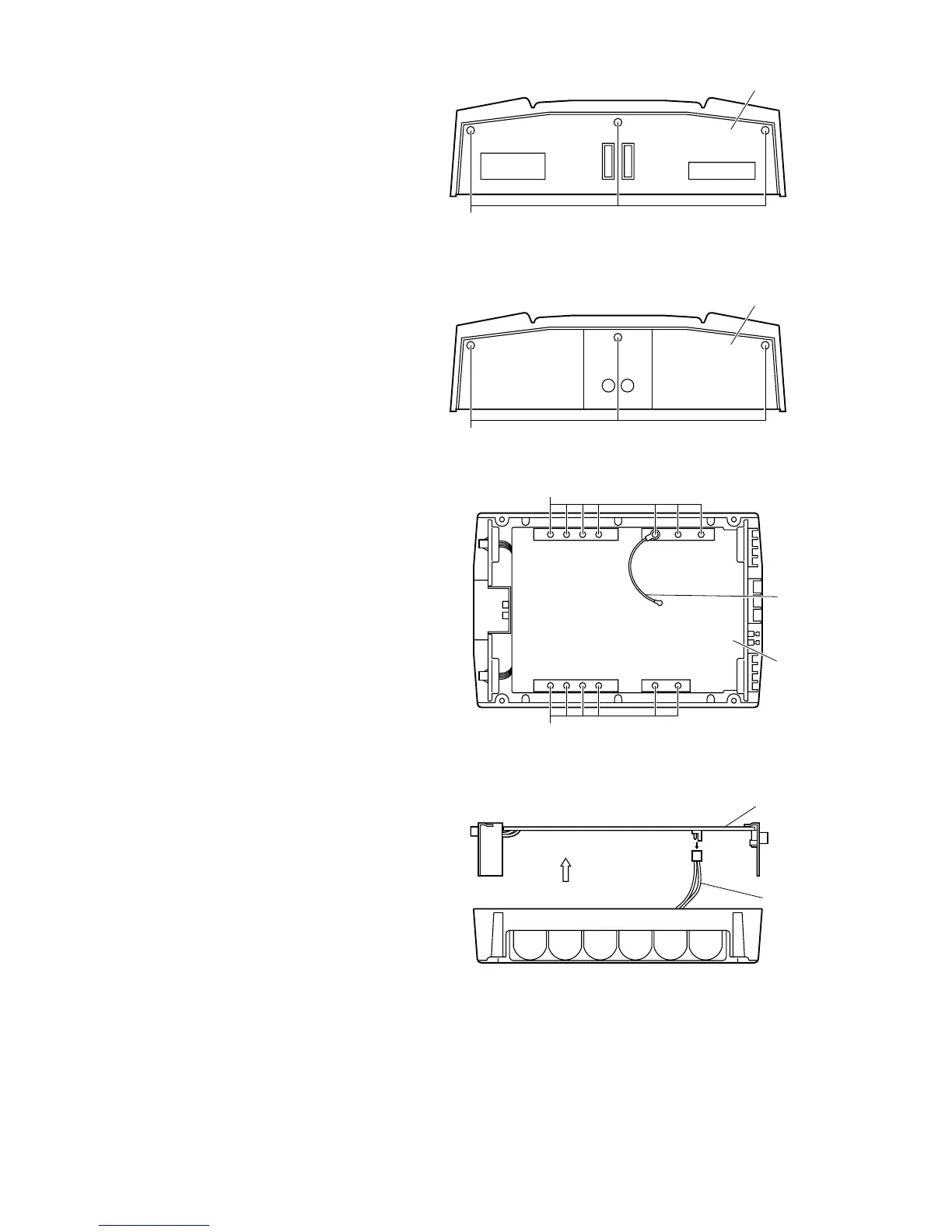
Remove the 6 screws E retaining the panels on both
sides of the main unit.
5.
To remove the wire ass'y, lift up the main P.C. board
a little.
7.
Remove the 13 screws F attaching the main P.C.
board to the bottom of the main unit.
(The GND wire that protrudes from the main
P.C.board must be re-installed to its original
position during re-assembly.)
6.
Fig. 7
Fig. 5
GND wire
Main P.C. board
Main P.C. board
Wire assemb'y
F
F
Rear panel
E
Fig. 6
Front panel
E
Fig. 8
(Side view)

 Loading...