EasyManua.ls Logo

JVC KW-XC55 User Manual

JVC KW-XC55
59 pages
To Next Page IconTo Next Page
Page #1 background imageLoading...
Page #1 background image
SERVICE MANUAL
COPYRIGHT © 2003 VICTOR COMPANY OF JAPAN, LIMITED
No.49784
2003/10
CD/CASSETTE RECEIVER
49784200310
KW-XC55
TABLE OF CONTENTS
1 PRECAUTION. . . . . . . . . . . . . . . . . . . . . . . . . . . . . . . . . . . . . . . . . . . . . . . . . . . . . . . . . . . . . . . . . . . . . . . . . 1-2
2 SPECIFIC SERVICE INSTRUCTIONS. . . . . . . . . . . . . . . . . . . . . . . . . . . . . . . . . . . . . . . . . . . . . . . . . . . . . . 1-4
3 DISASSEMBLY . . . . . . . . . . . . . . . . . . . . . . . . . . . . . . . . . . . . . . . . . . . . . . . . . . . . . . . . . . . . . . . . . . . . . . . 1-5
4 ADJUSTMENT . . . . . . . . . . . . . . . . . . . . . . . . . . . . . . . . . . . . . . . . . . . . . . . . . . . . . . . . . . . . . . . . . . . . . . . 1-23
5 TROUBLESHOOTING . . . . . . . . . . . . . . . . . . . . . . . . . . . . . . . . . . . . . . . . . . . . . . . . . . . . . . . . . . . . . . . . . 1-27
Area suffix
UN ----------------------------Asean
w
w
w
.
x
i
a
o
y
u
1
6
3
.
c
o
m
Q
Q
3
7
6
3
1
5
1
5
0
9
9
2
8
9
4
2
9
8
T
E
L
1
3
9
4
2
2
9
6
5
1
3
9
9
2
8
9
4
2
9
8
0
5
1
5
1
3
6
7
3
Q
Q
TEL 13942296513 QQ 376315150 892498299
http://www.xiaoyu163.com
Question and Answer IconNeed help?

Do you have a question about the JVC KW-XC55 and is the answer not in the manual?

JVC KW-XC55 Specifications

General IconGeneral
BrandJVC
ModelKW-XC55
CategoryCar Receiver
LanguageEnglish

Summary

Service Manual

Precaution

Safety precautions, including avoiding burrs and laser beam exposure.

Preventing Static Electricity

Measures against electrostatic discharge (ESD) to protect optical pickup components.

Disassembly

Main Body Disassembly

Procedures for disassembling the main body of the CD/cassette receiver.

Adjustment

Adjustment Method

Details on the adjustment method and required test instruments.

Troubleshooting

Service Mode Operations

How to enter and navigate the service mode menu.

Feed Section Troubleshooting

Troubleshooting guide for the feed section.

Focus Section Troubleshooting

Troubleshooting guide for the focus section.

Schematic Diagrams

Block Diagram

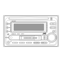
Visual representation of the system's components and their interconnections.

Standard Schematic Diagrams

Detailed electrical schematics of the unit's circuitry.

Main Amplifier Section

Detailed schematic for the main amplifier circuit.

CD Servo, LCD & Key Control Section

Schematic for CD servo, LCD, and key control circuits.

Parts List

Exploded View of General Assembly

Illustrated breakdown of the unit's main assemblies and parts.

Related product manuals