1-39
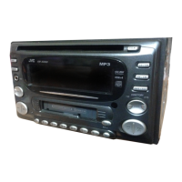
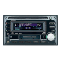
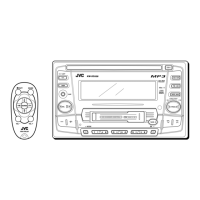
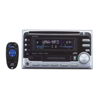
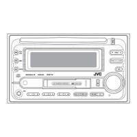
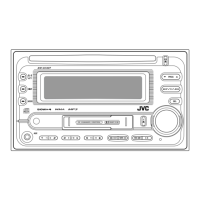
KW-XC828
2.Pin functions(2/2)
Pin No.
44~47
48
49
50
51
52
53
54
55
56~60
61
62
63
64
65
66~71
72
73~79
80
81
82
83
84
85
86
87
88
89
90
91
92
93
94
95~100
I/O
O
O
O
O
I
O
O
O
I
O
O
I/O
I/O
O
I
O
-
O
O
-
I
O
O
O
I
I
O
I
O
O
I
O
-
O
Non connect
Data input from EPROM
Data output to EPROM
EPROM Clock signal I/O
Stationdetector and stereo signal input terminal ("H" input at SD)
Chip enable output terminal to PLL
Data output terminal to PLL
Clock output terminal for communication to PLL
Data input terminal from PLL
Non connect
Non connect
Data I/O terminal to electric volume
Clock I/O terminal for communication to electric volume
Reset signal output terminalto LCD driver("L" output when resetting)
Outputs by "L" input the mute output terminal "L"
Non connect
(Connect with GND)
Non connect
Power is output " H" when it is on
(Connect with VDD)
Mute signal demand input terminal from CD mechanism
When the terminal RESET detects "L", 200mS "H"
(CD mechanism) (Reset output terminal is output)
Non connect
Non connect
Area setting of tuner 1
Area setting of tuner 2
Non connect
All lighring display of LCD by "L" input
Non connect
Non connect
Mute signal demandinput terminal from cassette mechanism
Reset output terminal to cassette mechanism
(When the terminal RESET detects "L", 200mS "H" is output)
GND and connects with 10k
Non connect
FunctionSymbol
NC
EPROM DI
EPROM DO
EPROM CK
SD/SI
PLL CE
PLLDATA
PLL CLK
PLL DI
NC
NC
E.VOL SO
E.VOL SCK
LCD RESET
TEL MUTE
NC
GND
NC
POWER ON
VDD
CD MUTE
CD RESET
NC
NC
AREA SET1
AREA SET2
NC
LCD TEST
NC
NC
CST MUTE
CST RESET
TEST
NC
UPD784215AGC173(2/2)
 Loading...