1-4
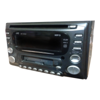
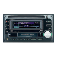
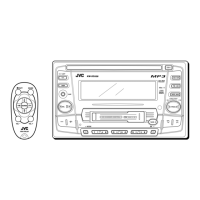
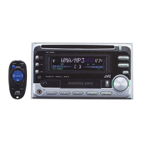
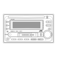
KW-XC828
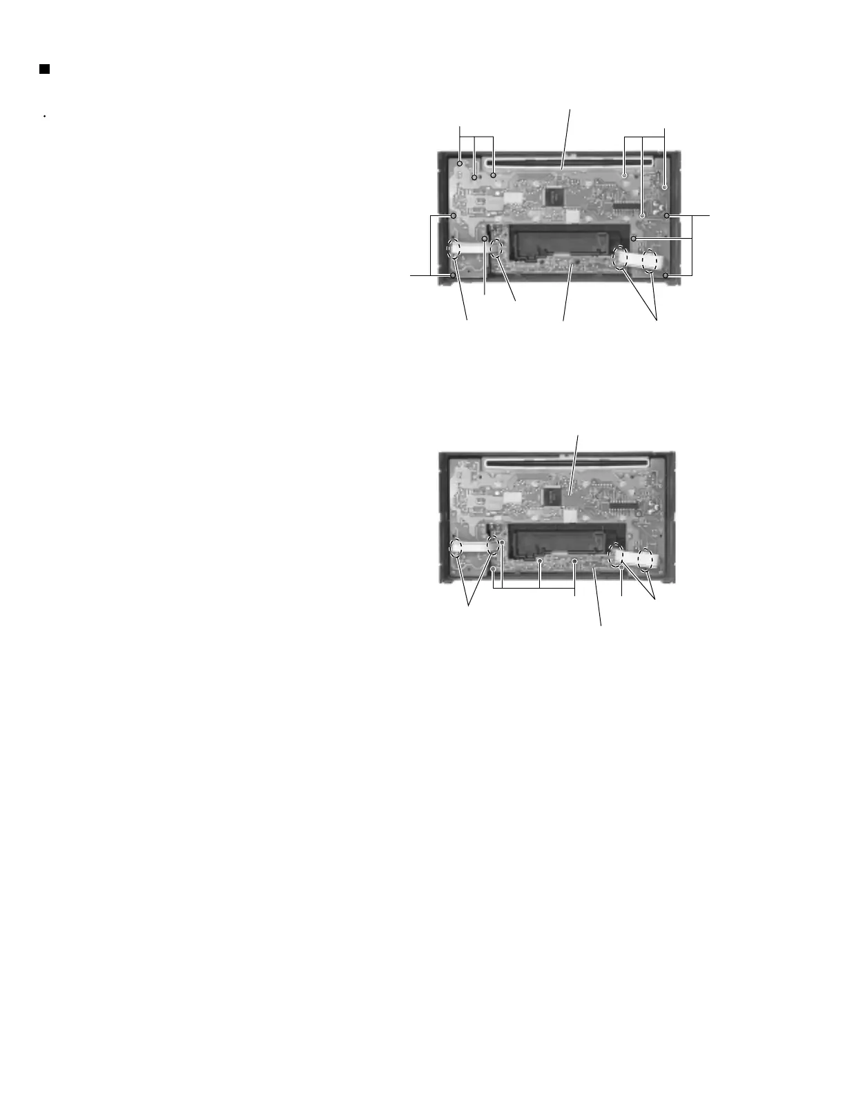
Prior to performing the following procedure, remove
the front panel assembly.
Remove the twelve screws B retaining the system
control board.
Remove the five screws C retaining the switch
board.
Unsolder WR501 and WR502 of the wires
connecting the system control board with the switch
board.
1.
2.
3.
Removing the system control board /
switch board (See Fig.4 , 5)
B
B
B
Switch board
Switch board
System control board
CC
B
WR502
WR502
WR501
WR501
WR502
Fig.4
Fig.5
System control board
B
 Loading...