1-10 (No.MA081)
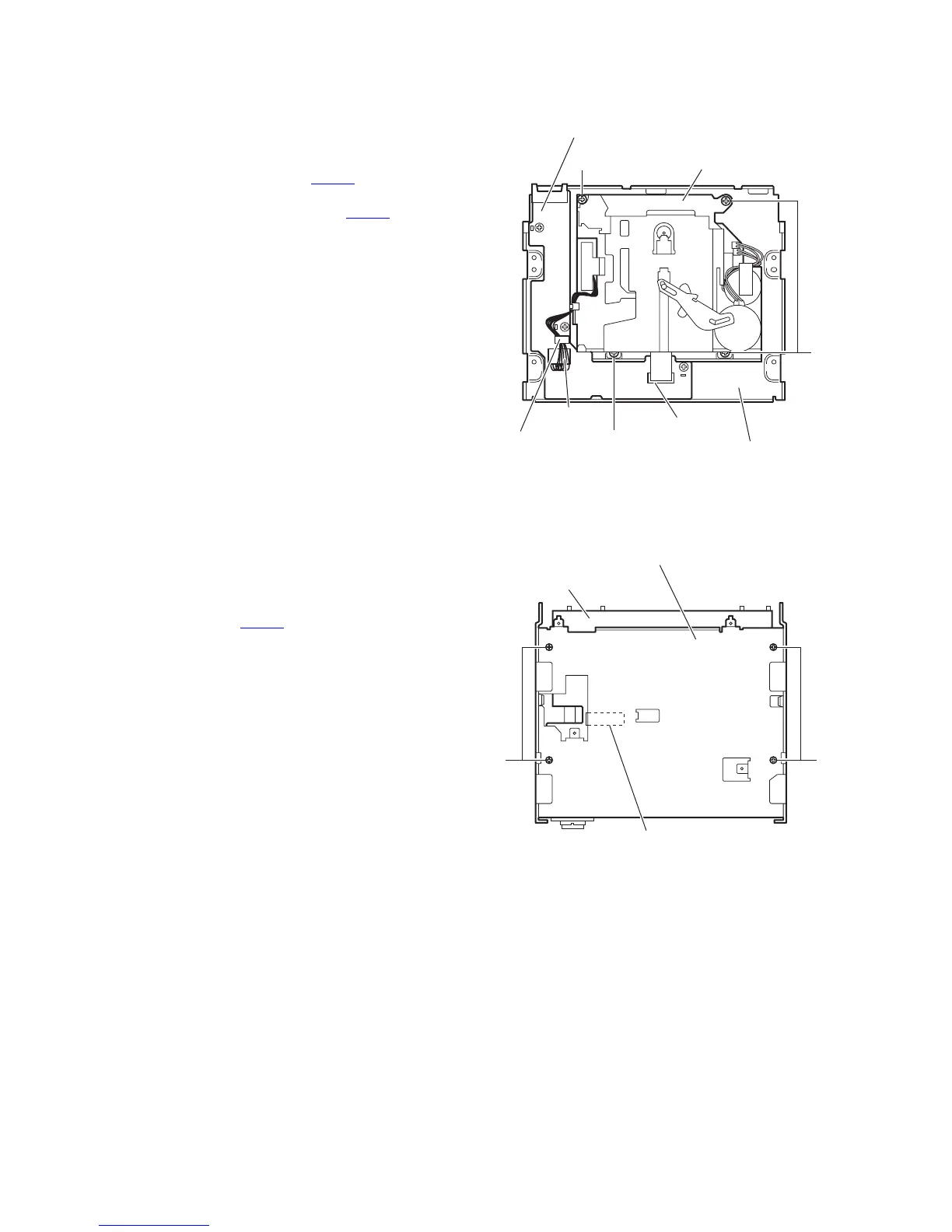
3.1.6 Removing the cassette mechanism assembly
(See Fig.7)
• Prior to performing the following procedures, remove the front
panel assembly, heat sink, rear bracket and bottom chassis
assembly.
(1) From the inside of the bottom chassis assembly, discon-
nect the card wire from the connector CN403
on the mech-
anism control board.
(2) Disconnect the wire from the connector CN402
on the
mechanism control board.
(3) Remove the four screws F attaching the cassette mecha-
nism assembly.
Reference:
After attaching the mechanism control board, fix the wire with
the wire clamp as before.
Fig.7
3.1.7 Removing the middle chassis assembly
(See Fig.8)
• Prior to performing the following procedures, remove the front
panel assembly, heat sink, rear bracket and bottom chassis
assembly.
(1) From the bottom side of the main body, remove the four
screws G attaching the middle chassis assembly.
(2) Disconnect the connector CN501
of the main board on the
middle chassis assembly from the CD mechanism assem-
bly in an upward direction.
Fig.8
CN403
CN402
Wire clamp
Mechanism control board
Bottom chassis assembly
F
F
F
Cassette mechanism assembly
Main board
Middle chassis assembly
GG
CN501
 Loading...