(No.YA509)1-15
3.2 MEMORY IC REPLACEMENT
• This model uses the memory IC.
• This memory IC stores data for proper operation of the video and drive circuits.
• When replacing, be sure to use an IC containing this (initial value) data.
3.2.1 MEMORY IC TABLE
3.2.2 MEMORY IC REPLACEMENT PROCEDURE
1. Power off
Switch off the power and disconnect the power plug from the AC outlet.
2. Replace the memory IC
Be sure to use the memory IC written with the initial setting values.
3. Power on
Connect the power plug to the AC outlet and switch on the power.
4. Receiving channel setting
Refer to the OPERATING INSTRUCTIONS and set the receive channels (Channels Preset) as described.
5. User setting
Check the user setting items according to the given in page later. Where these do not agree, refer to the OPERATING
INSTRUCTIONS and set the items as described.
6. SERVICE MODE setting
Verify what to set in the SERVICE MODE, and set whatever is necessary (Fig.3-2). Refer to the SERVICE ADJUSTMENT for
setting.
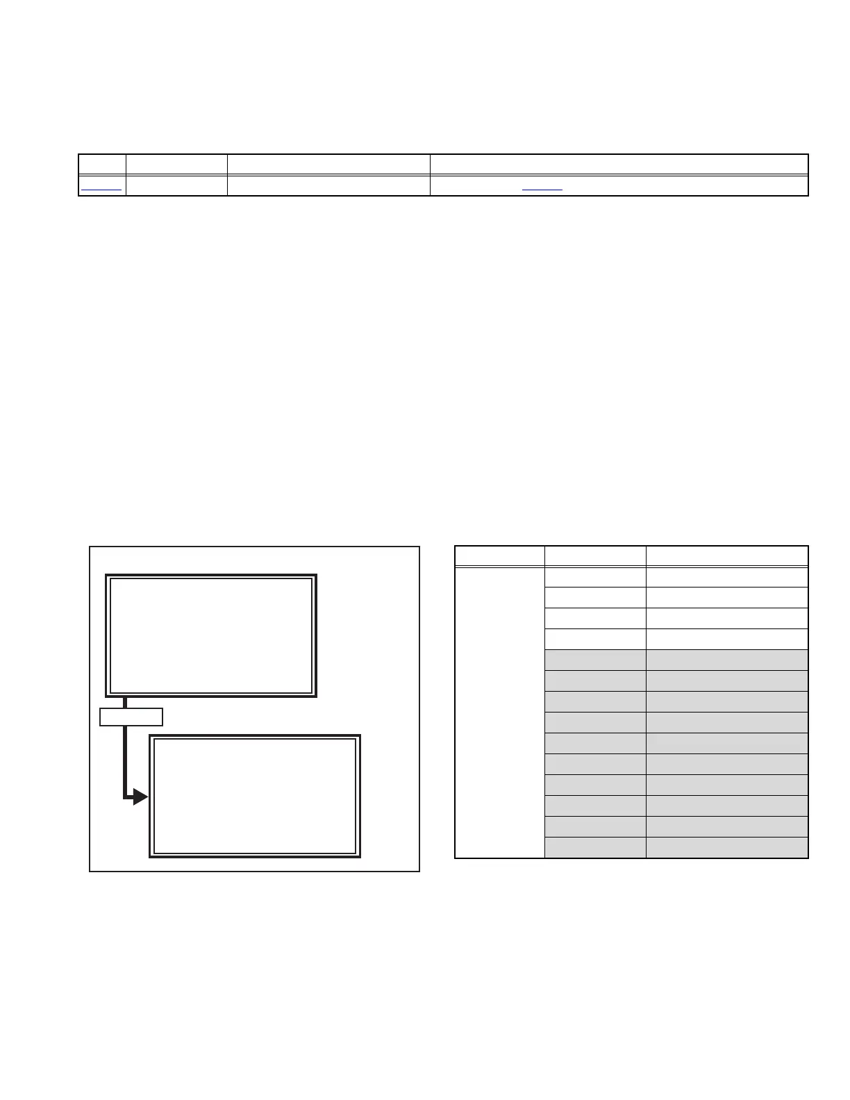
3.2.3 SERVICE MODE SETTING
SERVICE MODE SCREEN
Fig.3-2
SETTING ITEM
Simbol Number of pins Mounting PWB Main content of data
IC7003
8-pin MAIN PWB Setting value of IC7001(MAIN CPU) is memorized.
SERVICE MODE SCREEN
1. ADJUST
SERVICE MENU
1.ADJUST
2.SELF_CHECK
3.I2C STOP
Press [1] key
ADJUST
AUTO
FUL
1.SC ADJ
14
SC DEV:+ 0
- + OK:STORE i=EXIT
Setting mode Setting items Settings
1.ADJUST 1.SC ADJ. Adjust
2.R DRIVE Adjust
3.G DRIVE Adjust
4.B DRIVE Adjust
5.CUTOFF R Fixed [Do not adjust]
6.CUTOFF G Fixed [Do not adjust]
7.CUTOFF B Fixed [Do not adjust]
8.COLOUR Fixed [Do not adjust]
9.HUE Fixed [Do not adjust]
10.CONTRAST Fixed [Do not adjust]
11.BRIGHT Fixed [Do not adjust]
12.SHARP Fixed [Do not adjust]
13.DC EXTMD Fixed [Do not adjust]
14.PWM EXTMD Fixed [Do not adjust]
 Loading...