MX-DVB10
1-10
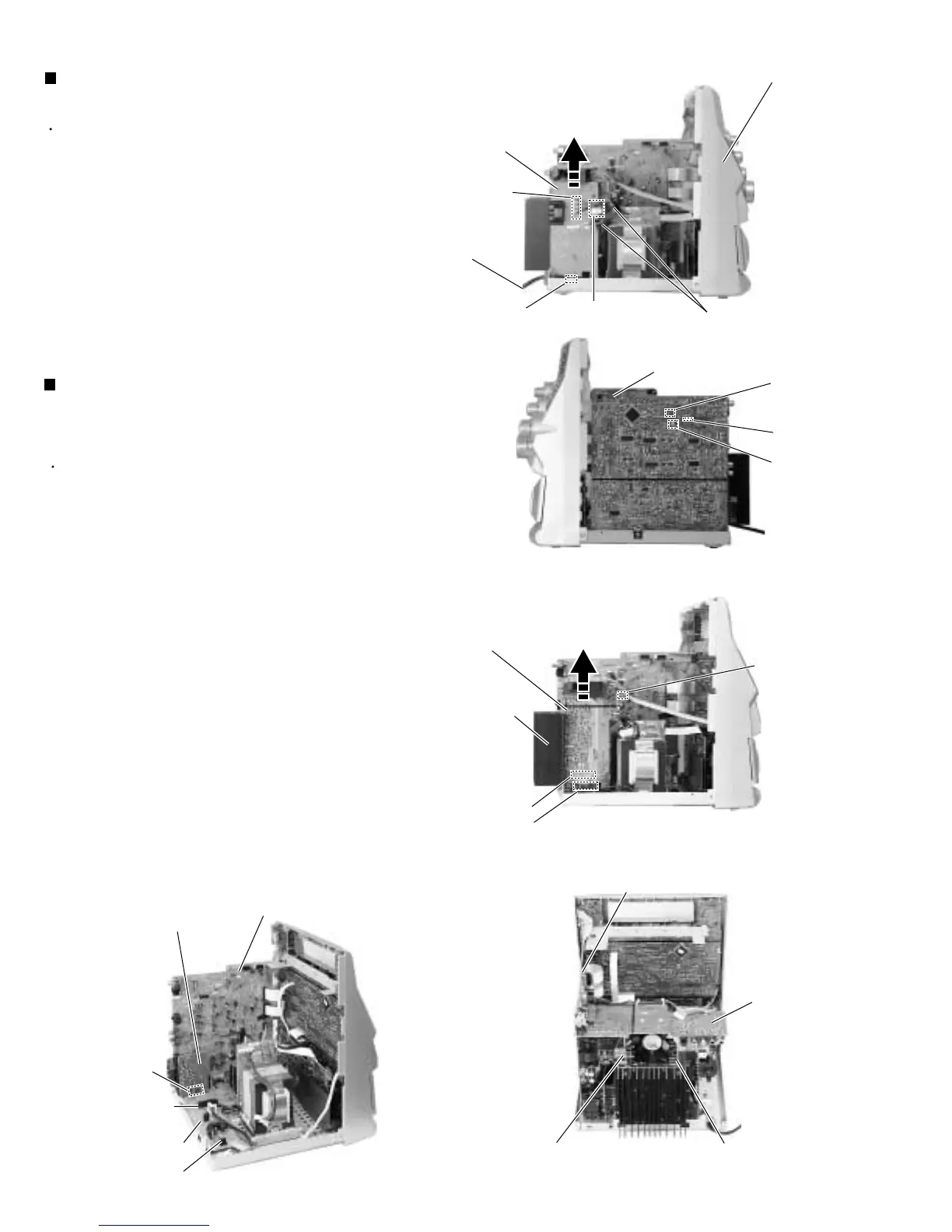
Prior to performing the following procedures, remove
the metal cover, the tuner board, the DVD changer
mechanism assembly, the p
ower supply
board and
the rear panel.
Removing the amplifier board (1, 2), AV
output board & speaker terminal board
(See Fig.18 to 21)
Remove the tie band marked b attaching the wire to
the AV output board.
Disconnect the card wire from the connector CN513
on the main board.
Disconnect the connector CN521 on the main board.
Disconnect the card wire from the connector CN703
on the amplifier board (2).
Disconnect the connectors CN205 and CN206 on
the amplifier board (1, 2) from the regulator board
(The heat sink and heat sink bracket will be
detached at once).
Disconnect the connector CN207 on the speaker
terminal
board from the regulator board.
1.
2.
3.
4.
5.
6.
Prior to performing the following procedures, remove
the metal cover, the tuner board, the DVD changer
mechanism assembly, the rear panel and the power
cord.
Removing the power supply board
(See Fig.17)
Remove the tie band marked a attaching the p
ower
supply
board.
Disconnect the connector CN218 and CN219 on the
p
ower supply board
.
Disconnect the connector CN203 on the p
ower supply
board
from the regulator board.
1.
2.
3.
Fig.17
Fig.18
Fig.20
Front panel assembly
Tie band
a
Amplifier board (1)
CN206
Regulator
board
Speaker terminal
board
Fig.19
CN203
Power supply
board
CN205
CN206
Fig.21
AV output
board
Tie band
b
CN513
CN521
CN205
Heat sink
Main board
Power cord
CN219
CN218
Main board
Amp. board (1)
Amp. board (2)
AV output
board
Main board
CN207
CN703