MX-DVB10
1-11
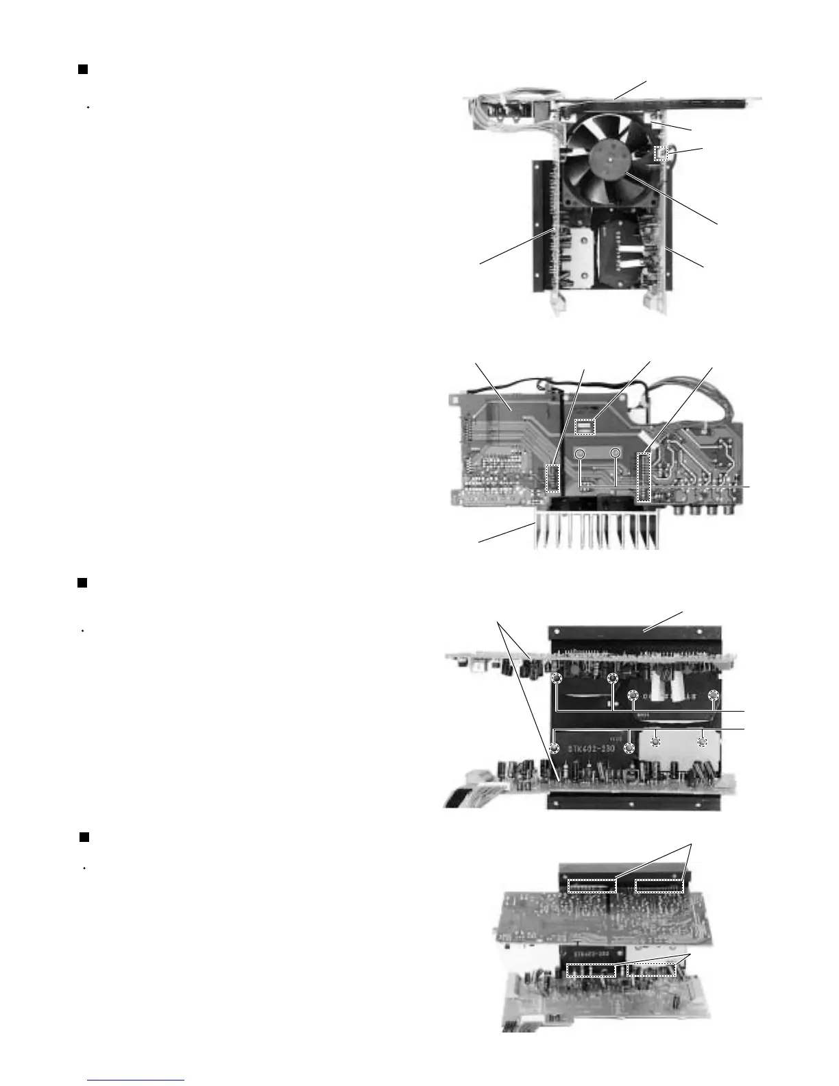
Prior to performing the following procedures, remove
the metal cover, the tuner board, the DVD changer
mechanism assembly, the rear panel, the amplifier
board (1,2) and the power supply board.
Disconnect the connector CN705, CN372 and
CN373 on the amplifier board (1, 2).
Remove the two screws marked J attaching the AV
output board to the fan bracket.
Pull out the fan bracket from the
AV output board.
Prior to performing the following procedures, remove
the metal cover, the tuner board, the power supply
board, the DVD changer mechanism, assembly the
rear panel, the tuner board, the amplifier board (1,2)
and AV output board.
Remove the eight screws marked K attaching the
ICs on the heat sink.
1.
Removing the Heat sink
(See Fig.24)
Prior to performing the following procedures, remove
the metal cover, the tuner board, the DVD changer
mechanism assembly, the rear panel, the tuner
board, the AV output board, the amplifier board (1,2),
the power supply board and the heat sink.
Unsolder the ICs s
older points
.
Remove the ICs.
1.
2.
Removing the ICs (See Fig.25)
1.
2.
3.
Removing the AV output board
(See Fig.22, 23)
Fig.22
Fig.23
Fig.24
CN705
Fan
AV output board
Hook
AV output board
J
CN373
CN372
Heat sink
Heat sink
K
K
Fig.25
Solder points
Solder points
Amp. board (1, 2)
Fan bracket
amplifier
board (1)
amplifier
board (2)