Do you have a question about the JVC MX-J100 and is the answer not in the manual?
Legal responsibility of the repairer to ensure safety standards are maintained.
General safety information for laser products, including warnings and cautions.
Grounding procedures for equipment and personnel to prevent static damage.
Guidelines for handling optical pickups and traverse units.
Notes on handling the CD mechanism assembly when decomposed.
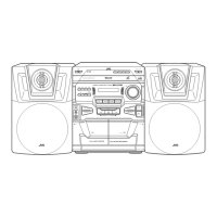
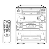
Steps to remove the top cover and side covers of the main body.
Method to eject the CD tray when the unit is not powered on.
Detailed steps for disconnecting and removing the CD changer unit.
Procedure for disconnecting harnesses and removing the front panel assembly.
Instructions for removing screws and detaching the rear panel.
Procedures for disconnecting harnesses and removing the mother (main) board.
Instructions for removing screws and detaching the heat sink cover plate.
Procedure for releasing tabs and disconnecting the tuner board.
Instructions for disconnecting power cords and removing the power transformer.
Procedure to remove screws and disconnect the power/CD switch board.
Steps to pull out the volume knob and remove the system board.
Procedure to remove the system board temporarily and detach the headphone board.
Disconnecting card wire and removing screws for the cassette mechanism assembly.
Turning pulley gear and pushing stoppers to remove the CD tray.
Aligning gears and mounting the CD tray correctly.
Releasing tabs, disconnecting harness, and removing the sensor board and tray motor assembly.
Detaching belt, disconnecting wires, and removing servo/switch boards.
Disconnecting harness, removing screws, and pulling out the mechanism holder assembly.
Loosening screws, removing gear stopper, and pulling out the pickup unit.
Unsoldering motor terminal and removing the motor board.
Remove motor fixing screws to detach the feed motor.
Spindle motor must be changed with the chassis and turntable as a unit.
Remove screws to detach the record/playback (R/P) head.
Remove the screw fixing the erase head.
Pull out the pinch roller by opening its stopper.
Remove screws and unsolder motor terminal to detach the motor.
Unsoldering terminals and removing screws to detach the mechanism board.
Remove cut-washers from the capstan shaft to remove the flywheel.
Adjustment procedures for the tuner section of the PCB.
Identifies adjustment points on the Tuner PCB.
Adjusting the FM detector coil for minimum distortion.
Adjusting sensitivity to light the "TUNED" indicator.
Adjusting the AM I.F Coil for maximum output.
Procedure for adjusting tape speed using a frequency counter.
Adjusting the play level for Deck A, securing with region lock.
Adjusting Deck B play level and recording bias voltage.
Steps and check points for reading the Table of Contents (TOC).
Instructions for cleaning the pickup lens with a cotton swab.
Steps for replacing the laser pickup, including power off and eye-pattern check.
Warning against adjusting the semi-fixed resistor for laser power.
Detailed function block diagram of the LC75341 IC.
Block diagram and function of the LC72131D PLL IC.
Block diagram of the STK402-040 amplifier IC.
Pinout and function of the LA1837 FM/AM IF/DET IC.
Block diagram of the KS9286B DSP/D-A converter IC.
Detailed block diagram for the KB9223 CD RF ASSP.
Block diagram of the KA9258D 4-channel motor driver IC.
Block diagram of the KA22291 cassette amplifier IC.
| Power Output | 100 W |
|---|---|
| Speakers | 2 |
| Inputs | AUX |
| Outputs | Headphone Jack |
| Functions | CD Player, Radio |