MX-J270V
1-11
Prior to performing the following procedure, remove
the metal cover, the CD changer mechanism
assembly and the front panel assembly.
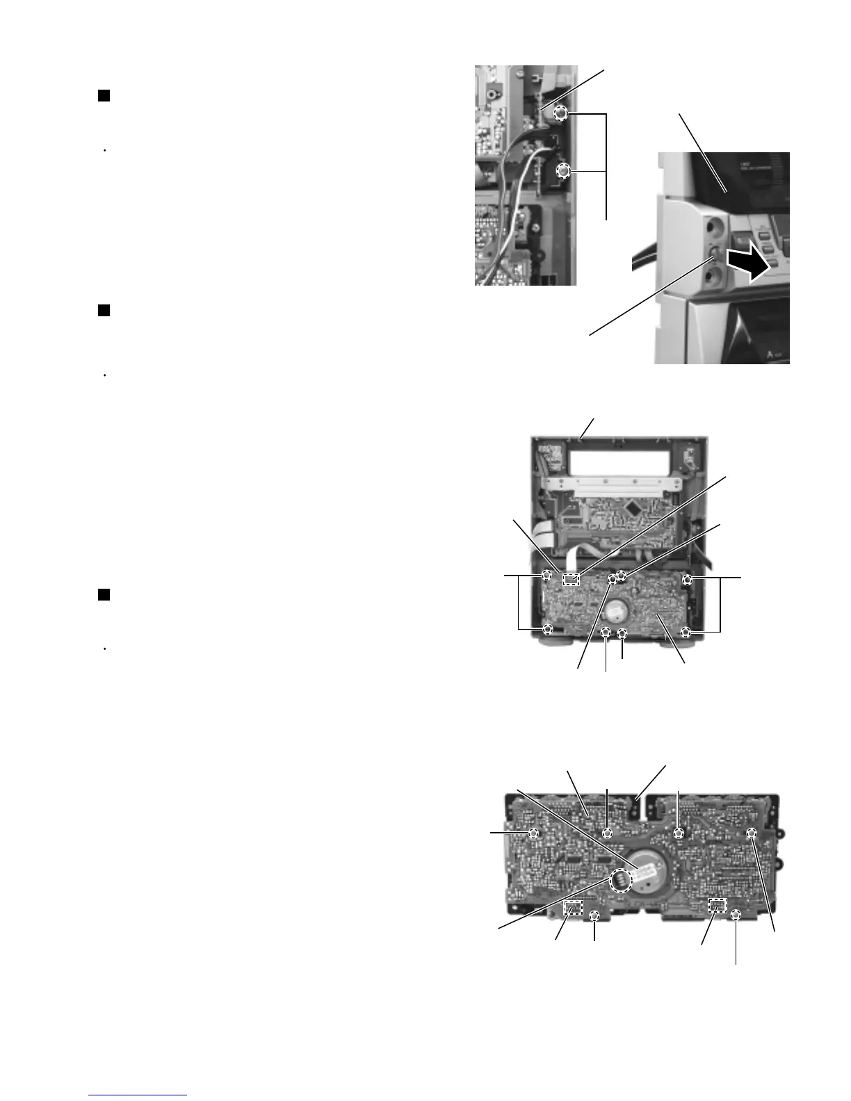
Remove the two screws P attaching the MIC
/headphone board.
Pull out the MIC LEVEL knob from front side.
Prior to performing the following procedure, remove
the metal cover, the CD changer mechanism
assembly and the front panel assembly.
Disconnect the card wire from connector CN305 on
the cassette amplifier board.
Remove the eight screws Q attaching the cassette
mechanism assembly.
Detach the cassette mechanism assembly toward
you.
1.
2.
1.
2.
3.
Prior to performing the following procedure, remove
the cassette mechanism assembly.
Disconnect the card wire from connector CN301 and
CN302 on the cassette amplifier board.
Remove the six screws R attaching the cassette
amplifier board.
Unsolder the soldering k on the harness for the DC
motor.
Detach the cassette amplifier board toward you.
1.
2.
3.
4.
<Front panel assembly>
Removing the MIC/headphone board
(See Fig.23 and 24)
Removing the cassette mechanism
assembly
(See Fig.25)
Removing the cassette amplifier board
(See Fig.26)
Fig.25
Fig.23
Fig.24
Fig.26
Q
Q
Q
Q
Cassette
mechanism
assembly
Cassette amplifier board
CN302
CN301
Cassette mechanism
board
DC motor
P
MIC/headphone board
MIC LEVEL knob
Q
Q
CN305
Cassette amplifier
board
R
R
R
R
R
R
Soldering k
Front panel assembly
Front panel assembly
 Loading...