MX-K1
1-6
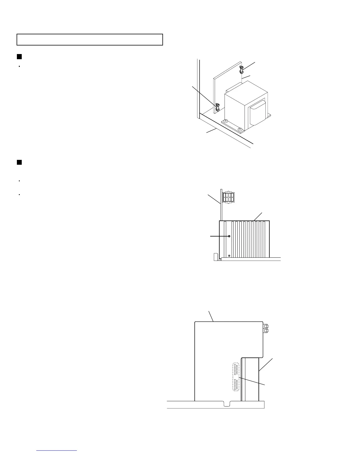
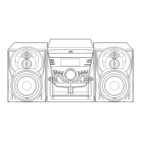
Fig.1
[Caution] Be sure to use fuses with the specified
ratings.
Replacing the fuses (See Fig.1)
1.
Prior to performing the following procedure, remove
the top cover.
Replace the fuses inside.
1.
2.
Prior to performing the following procedure, remove
the top cover.
Also remove the rear panel. (See Fig.33)
Remove the screw "A" from the bracket that retains
the power IC.
Remove the solder fixing the power IC.
Replacing the power IC
(See Fig.2 and 3)
Fig.3
Fig.2
<Disassembly of the main blocks of this set>
Replacement of the fuses and the power IC
A
Heat sink
Power amp
and supply PCB
Fuse (F951)
1A 250V
Power trans PCB
Fuse (F952)
1.6A 250V
Chassis
Power amp and supply PCB
Power IC
soldering part
Heat sink