1 HEAD AZIMUTH ADJUSTMET
( 1 ) Load the test tape TCC-182A 8KHz for azimuth
adjustment.
( 2 ) Press the PLAY button.
( 3 ) Use a cross-tip screwdriver to turn the screw for azimuth
adjustment so that the left and right output are maximized
( 4 ) Press the STOP button
( 5 ) After completion of the adjustment. Use thread lock(TB-1401B)
to secure the azimuth-adjustment screw.
2 AC BIAS FREQUENCY ADJUSTMENTS
( 1 ) Connect frequency counter to CN202(BS);
( 2 ) R/P swith in recording state;
( 3 ) Adjusting T801 use a plastic screwdriver, AC bias frepuency ;61kHz +/- 1kHz..
3 TAPE SPEED ADJUSTMENT
( 1 ) Insert the test tape(MTT-111N,3,000 HZ)
( 2 ) Press the PLAY button.
( 3 ) Use a flat-tip screwdriver to turn the VR 501.
Adjust VR501 so that the frequency counter
become 3,000Hz
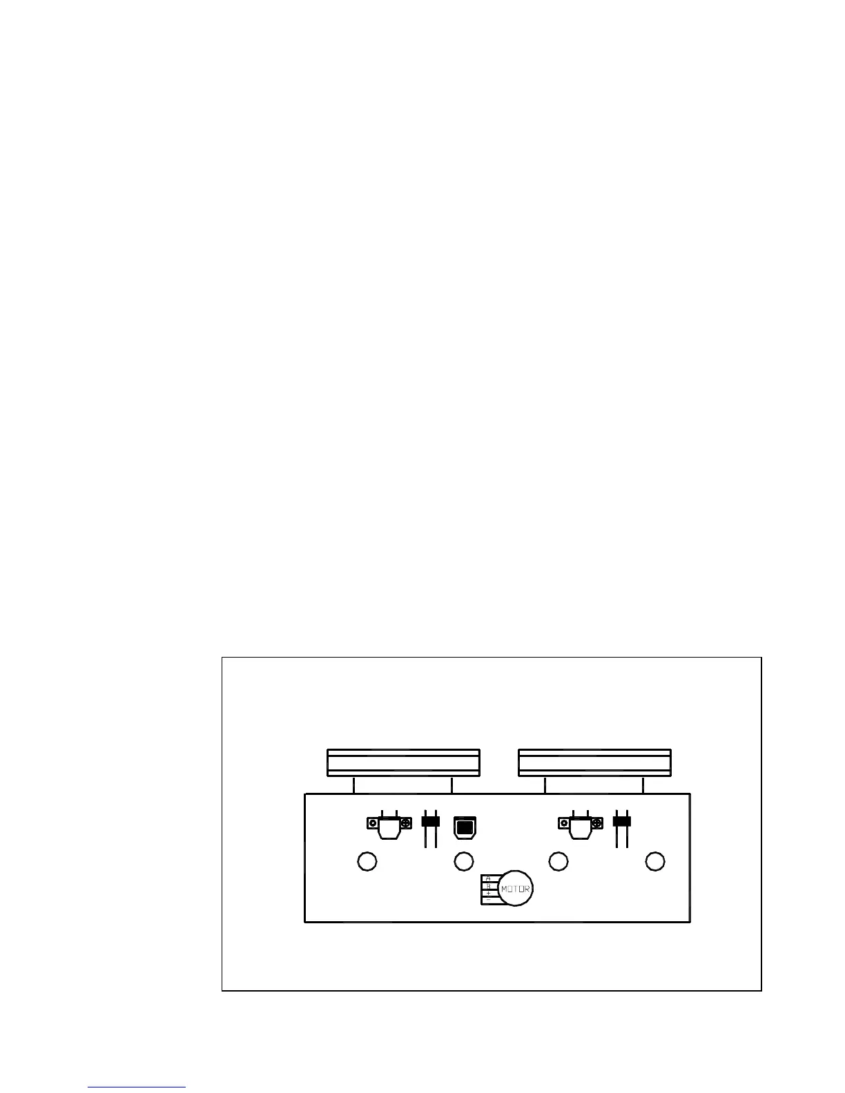
TAPE HEAD AND SPEED ADJUSTMENT DIAGRAM
CASS DECK
A DECK B DECK
A
P HEAD
L. SW
A
L. SW
E HEAD
P/R HEAD
PC-X250
1 - 7