ADJUSTMENT
~
The following four adjustments are recommended only in the
event that you have replaced a cartridge or a headshell.
Otherwise, no adjustments are required.
Note: If you change the cartridge, it is recommended to use
the headshell provided on this unit.
~~~
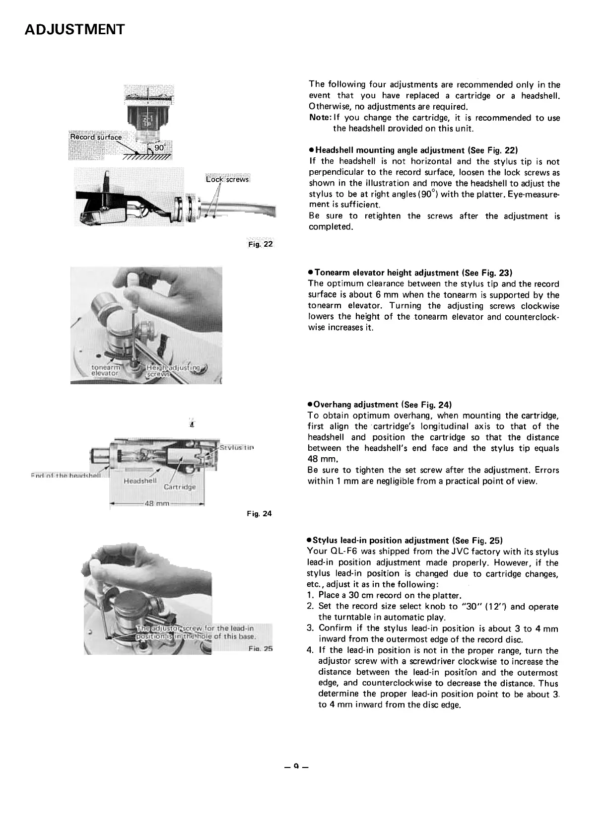
.Headshell mounting angle adjustment (See Fig. 22)
If the headshell is not horizontal and the stylus tip is not
perpendicular to the record surface, loosen the lock screws as
shown in the illustration and move the headshell to adjust the
stylus to be at right angles (900) with the platter. Eye-measure-
ment is sufficient.
Be sure to retighten the screws after the adjustment is
completed.
Fig. 22
.Tonearm elevator height adjustment (See Fig. 23)
The optimum clearance between the stylus tip and the record
surface is about 6 mm when the tonearm is supported by the
tonearm elevator. Turning the adjusting screws clockwise
lowers the height of the tonearm elevator and counterclock-
wise increases it.
j
4
.Overhang adjustment (See Fig. 24)
To obtain optimum overhang, when mounting the cartridge,
first align the cartridge's longitudinal axis to that of the
headshell and position the cartridge so that the distance
between the headshell's end face and the stylus tip equals
48mm.
Be sure to tighten the set screw after the adjustment. Errors
within 1 mm are negligible from a practical point of view.
Fig.24
.Stylus lead-in position adjustment (See Fig. 25)
Your OL.F6 was shipped from the JVC factory with its stylus
lead-in position adjustment made properly. However, if the
stylus lead-in position is changed due to cartridge changes,
etc., adjust it as in the following:
1. Place a 30 cm record on the platter .
2. Set the record size select knob to "30" ( 12") and operate
the turntable in automatic play.
3. Confirm if the stylus lead.in position is about 3 to 4 mm
inward from the outermost edge of the record disc.
4. If the lead.in position is not in the proper range, turn the
adjustor screw with a screwdriver clockwise to increase the
distance between the lead-in position and the outermost
edge, and counterclockwise to decrease the distance. Thus
determine the proper lead-in position point to be about 3,
to 4 mm inward from the disc edge.
-Q-
 Loading...