(No.MB279)1-5
SECTION 3
DISASSEMBLY
3.1 Main body
3.1.1 Removing the rear cover assembly section
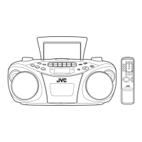
(See Fig.1 to 3)
(1) Remove the eight screws A, the three screws B and the
four screws C attaching the rear cover assembly on the
back of the body.
(2) Remove the battery cover on the back of the body and re-
move the two screws D attaching the rear cover assembly.
(3) Move the rear cover assembly in the direction of the arrow
and remove. At this time, disconnect the wire from connec-
tor CN406
and FM-ANT on the main board.
Fig.1
Fig.2
Fig.3
C
B
C
A
D
A
A
D
Battery cover
FM-ANT
Top cover assembly
Rear cover assembly
Tuner board
CN406
Front panel assembly
Main board

 Loading...