1-6 (No.MB279)
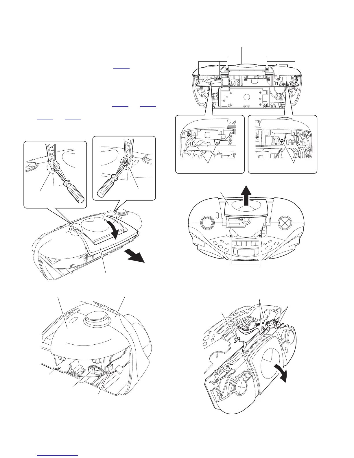
3.1.2 Removing the top cover assembly section and the front panel assembly section
(See Fig.4 to 8)
• Prior to performing the following procedure, remove the rear
cover assembly.
(1) Release the tab a of the handle using a screwdriver. Return
the handle below and pull out in the direction of the arrow.
(2) Disconnect the wire from connector CN404
and 4pin con-
nector on the main board.
(3) Remove the six screws E and the two screws F attaching
the top cover.
(4) Draw out the top cover assembly from the front panel as-
sembly section backward.
(5) Disconnect the wire from connector CN501
and CN506 on
the main board, and disconnect the card wire from connec-
tor CN507
and CN508.
(6) Disconnect the wire from board connector CON301 of the
cassette mechanism assembly.
Fig.4
Fig.5
Fig.6
Fig.7
Fig.8
tab a
tab a
Handle
CN404
Main board
4pin connector
Front panel assembly
Top cover assembly
E
Top cover assembly
E
EE
CD door
F
Main board
CN501,CN506
Main board
CN508,CN507
Cassette mechanism board
CON301
 Loading...