RX-6000VBK/RX-6008VBK/RX-6100VBK
2-6
Prior to performing the following procedure, remove
the top cover and the front panel.
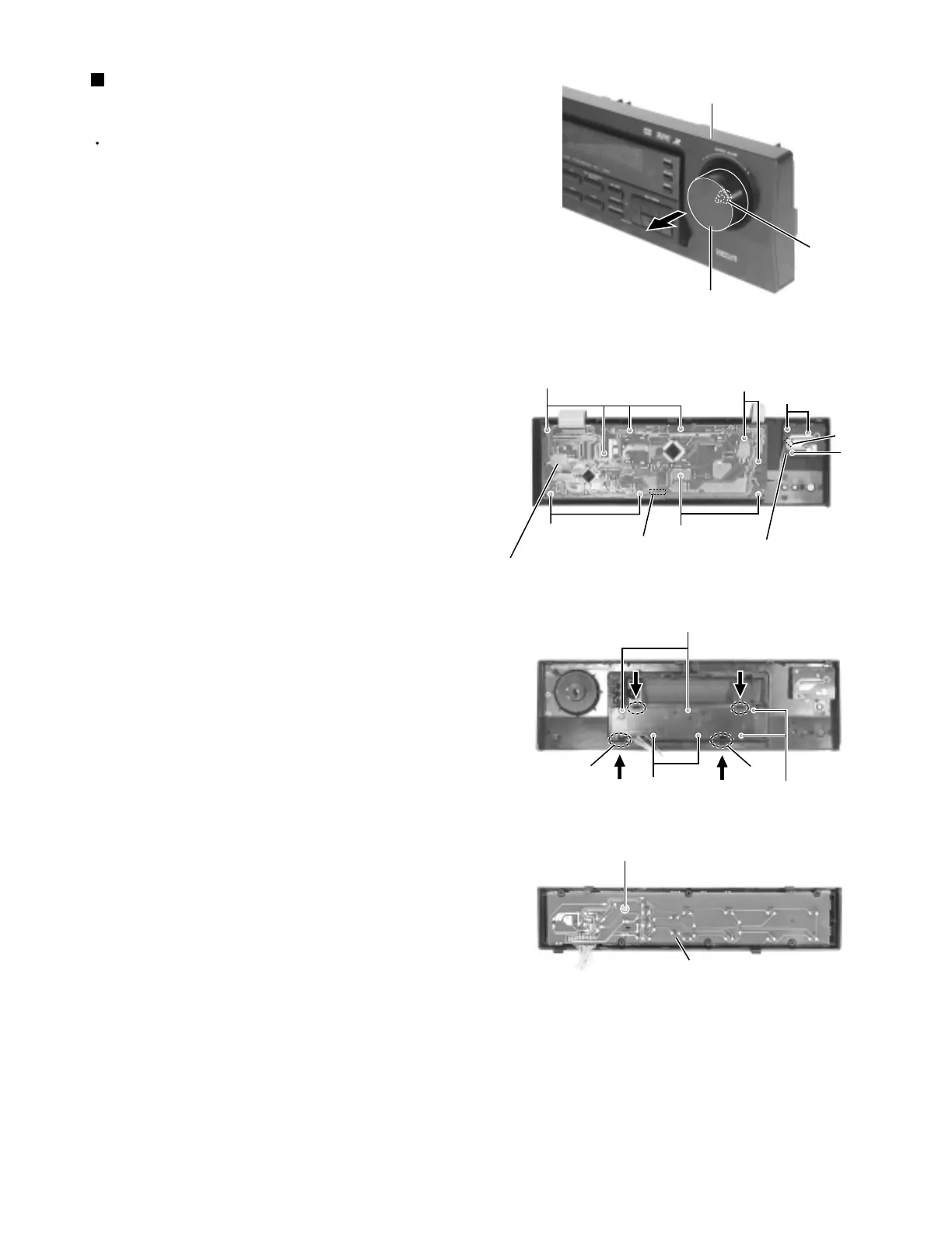
Pull out the volume knob on the front side of the front
panel and remove the nut attaching the volume
board.
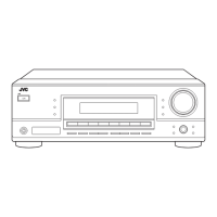
Remove the three screws N attaching the volume
board on the back of the front panel and disconnect
the harness from connector CN411 on the volume
board.
Remove the ten screws O attaching the system
control board and disconnect the harness from
connector CN402 on the system control board.
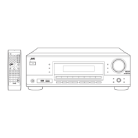
Remove the six screws P attaching the operation
switch board. Push each tab b of the four joints
inward and detach the operation switch board to the
front.
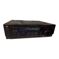
Remove the screw Q attaching the operation switch
board.
1.
2.
3.
4.
5.
Removing each board in the front panel
assembly (See Fig.17 to 20)
Fig.20
Fig.19
Fig.18
Fig.17
System control board
Q
P
P
Tab b
Tab b
P
O
O
O
O
N
N
Volume board
CN402
CN411
System control board
Volume knob
Nut
Front panel assembly