RX-6030VBK
(No.22026)1-5
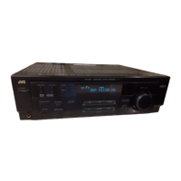
2.3 Removing the rear panel
(See Fig.4)
• Prior to performing the following procedure, remove the top
cover.
(1) From the back side of the main body, remove the strain re-
lief from the rear panel in the direction of the arrow.
(2) Remove the twenty-five screws E and four screws F at-
taching the rear panel.
Fig.4
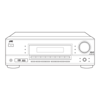
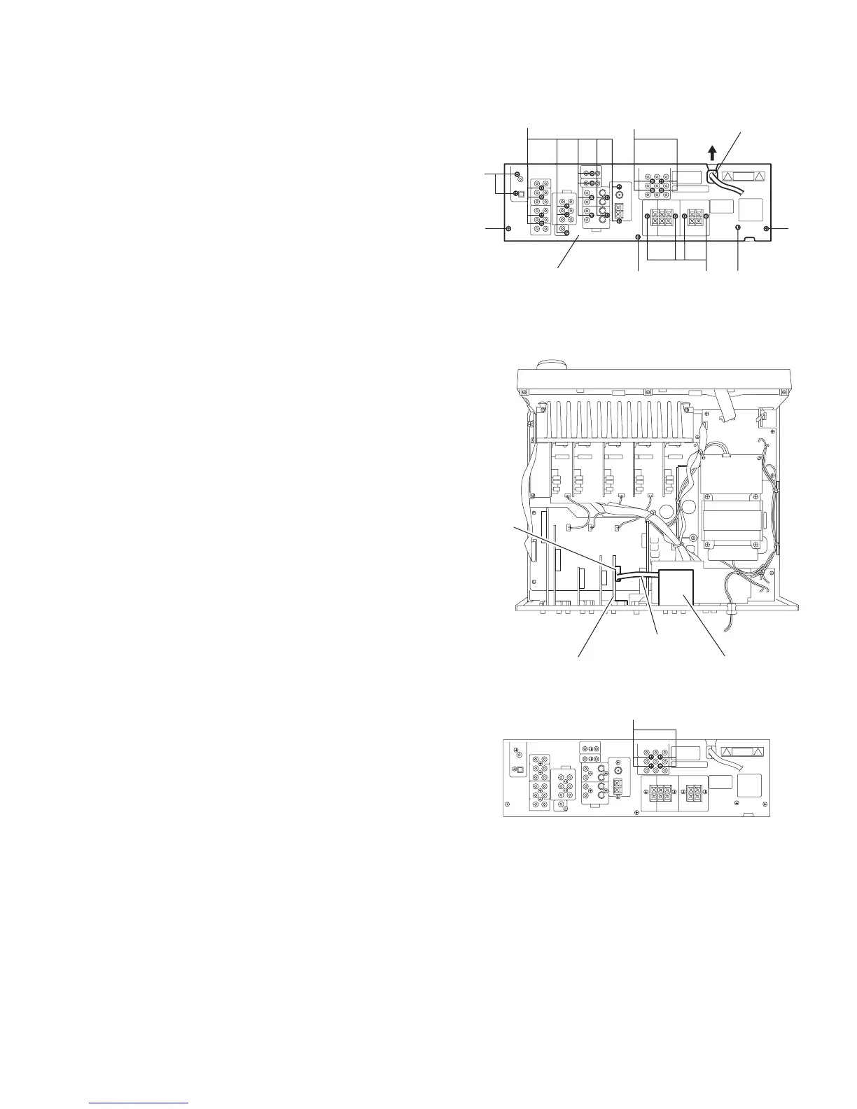
2.4 Removing the component board
(See Figs.5 and 6)
• Prior to performing the following procedure, remove the top
cover.
(1) From the top side of the main body, disconnect the parallel
wire from the connector CN511 on the S Video board. (See
Fig.5)
(2) From the back side of the main body, remove the four
screws G attaching the component board. (See Fig.6)
Fig.5
Fig.6
E
E
F
E
EFF
F
Strain relief
Rear panel
CN511
S Video board
Parallel wire
Component board
G
 Loading...