RX-8010RBK/ RX-8012RSL
1-3
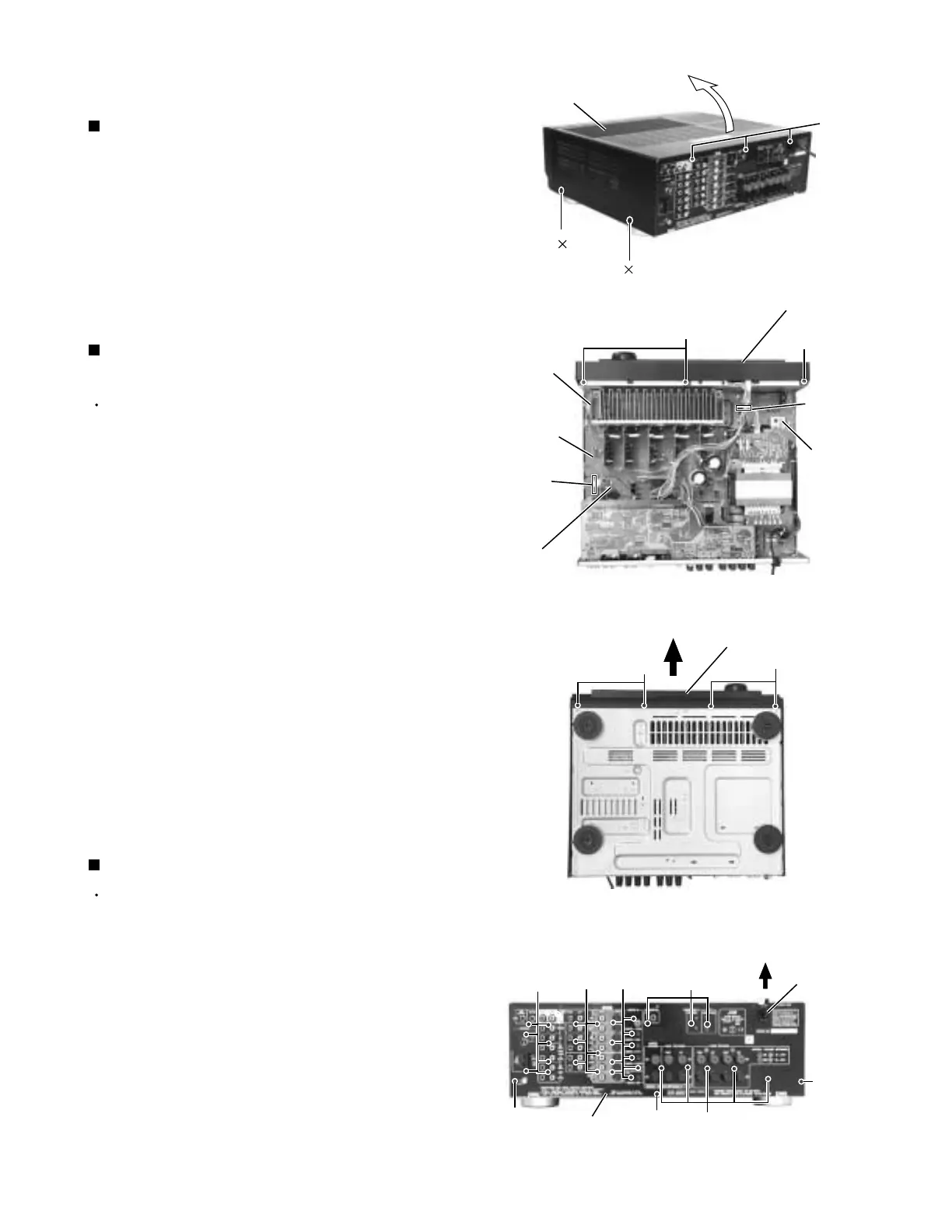
Remove the four screws A attaching the top cover
on both sides of the body.
Remove the three screws B on the back of the body.
Remove the top cover from behind in the direction of
the arrow while pulling both sides outward.
1.
2.
3.
Disassembly method
Removing the top cover (See Fig.1)
Prior to performing the following procedure, remove
the top cover.
Remove the power cord stopper from the rear panel
by moving it in the direction of the arrow.
Remove the thirty one screws E attaching the each
boards to the rear panel on the back of the body.
Remove the three screws F attaching the rear panel
on the back of the body.
1.
2.
3.
Removing the rear panel (See Fig.4)
Prior to performing the following procedure, remove
the top cover.
Disconnect the card wire from connector CN400 on
the audio board and CN402 on the power supply
board in the front panel assembly.
Cut off the tie band fixing the harness.
Remove the three screws C attaching the front
panel assembly.
Remove the four screws D attaching the front panel
assembly on the bottom of the body. Detach the front
panel assembly toward the front.
1.
2.
3.
4.
Removing the front panel assembly
(See Fig.2 and 3)
Fig.1
Fig.2
Fig.3
Fig.4
A
2
A 2
B
Top cover
C
Power
supply
board
Audio board
CN400
Main
board
Tie band
D
E
F
E
F
F
Cord stopper
C
Front panel assembly
Front panel assembly
D
Rear panel
CN402
EE
E
 Loading...