1-6 (No.MB103)
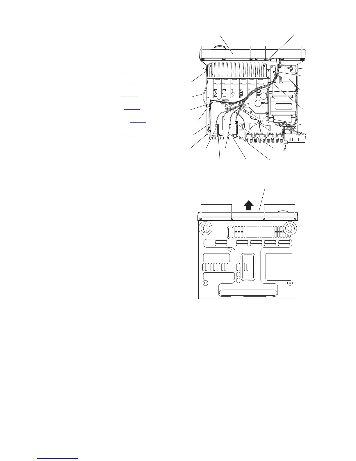
3.4 Removing the front panel assembly
(See Figs.4 and 5)
• Prior to performing the following procedures, remove the top
cover, rear panel and I/O board.
(1) From the top side of the main body, remove the tie bands
bundling the wires. (See Fig.4)
(2) Disconnect the wire from the connector CN599
on the DSP
board. (See Fig.4)
(3) Disconnect the wire from the connector CN415
on the
Audio2 board. (See Fig.4)
(4) Disconnect the wire from the connector CN206
on the Vid-
eo board. (See Fig.4)
(5) Disconnect the wire from the connector CN244
on the S-
Video board. (See Fig.4)
(6) Disconnect the card wire from connector CN402
on the
power supply board. (See Fig.4)
(7) Disconnect the card wire from connector CN400
on the mi-
con board. (See Fig.4)
(8) Remove the tie band and wire protection board fixing the
card wire. (See Fig.4)
(9) Remove the three screws F and screw G attaching the front
panel assembly. (See Fig.4)
REFERENCE :
When attaching the screw G, attach the earth wire with it.
(10) From the bottom side of the main body, remove the four
screws H attaching the front panel assembly. (See Fig.5)
(11) Remove the front panel assembly in the direction of the ar-
row. (See Fig.5)
Fig.4
Fig.5
F
F
F
G
Front panel assembly Earth wire
CN402
Power
supply
board
Tie
band
Tie
band
Micon
board
CN244
S-Video boardVideo board
CN206CN415
Audio2 board
CN599
DSP
board
CN400
Tie
band
Card
wire
Tie
band
Wire
protection
board
HH
Front panel assembly
 Loading...