(No.MB103)1-9
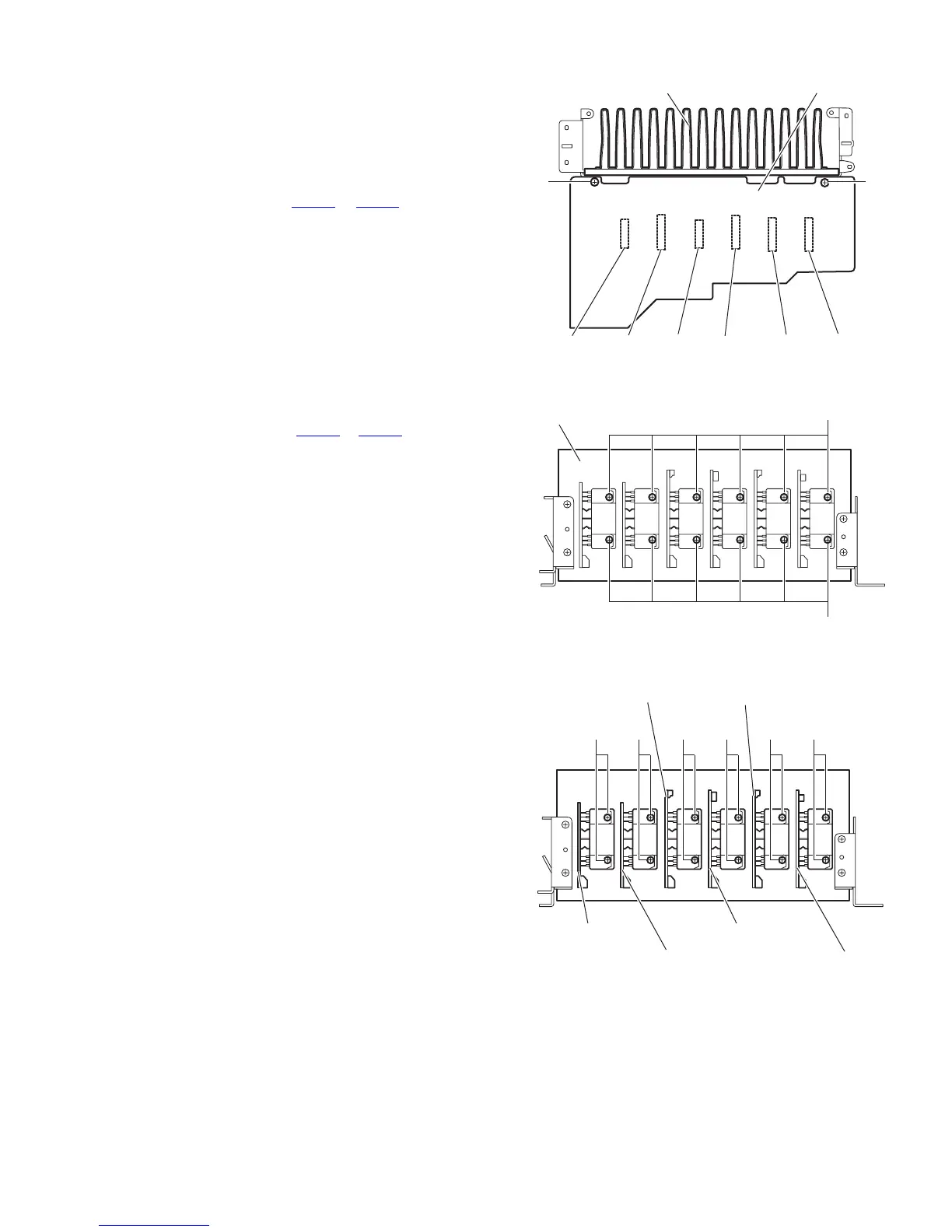
3.9 Removing the heat sink
(See Figs.10 and 11)
• Prior to performing the following procedures, remove the top
cover and main board.
(1) From the reverse side of the main board, remove the two
screws P attaching the main board to the heat sink. (See
Fig.10)
(2) Disconnect the connector (CN701
to CN706) on the main
board, remove the main board. (See Fig.10)
(3) Remove the twelve screws Q attaching the heat sink. (See
Fig.11)
3.10 Removing the center board, front boards (L/R),
surround boards (L/R) and surround back board
(See Figs.10 and 12)
• Prior to performing the following procedures, remove the top
cover and main board.
(1) From the reverse side of the main board, remove the two
screws P attaching the main board to the heat sink. (See
Fig.10)
(2) Disconnect the connectors (CN701
to CN706) on the main
board, remove the main board. (See Fig.10)
(3) Remove the two screws Q attaching the center board. (See
Fig.12)
(4) Remove the two screws Q attaching the front board (L).
(See Fig.12)
(5) emove the two screws Q attaching the surround back
board. (See Fig.12)
(6) Remove the two screws Q attaching the front board (R).
(See Fig.12)
(7) Remove the two screws Q attaching the surround board
(L). (See Fig.12)
(8) Remove the two screws Q attaching the surround board
(R). (See Fig.12)
Fig.10
Fig.11
Fig.12
Heat sink
Main board
CN703 CN701 CN704 CN702 CN705 CN706
P
P
Heat sink
Q
Q
Surround board(R)
Q Q Q Q Q Q
Surround board(L)
Front board(R)
Surround back board
Front board(L)
Center board
 Loading...