(No.MB368)1-17
3.1.8 Removing the main board
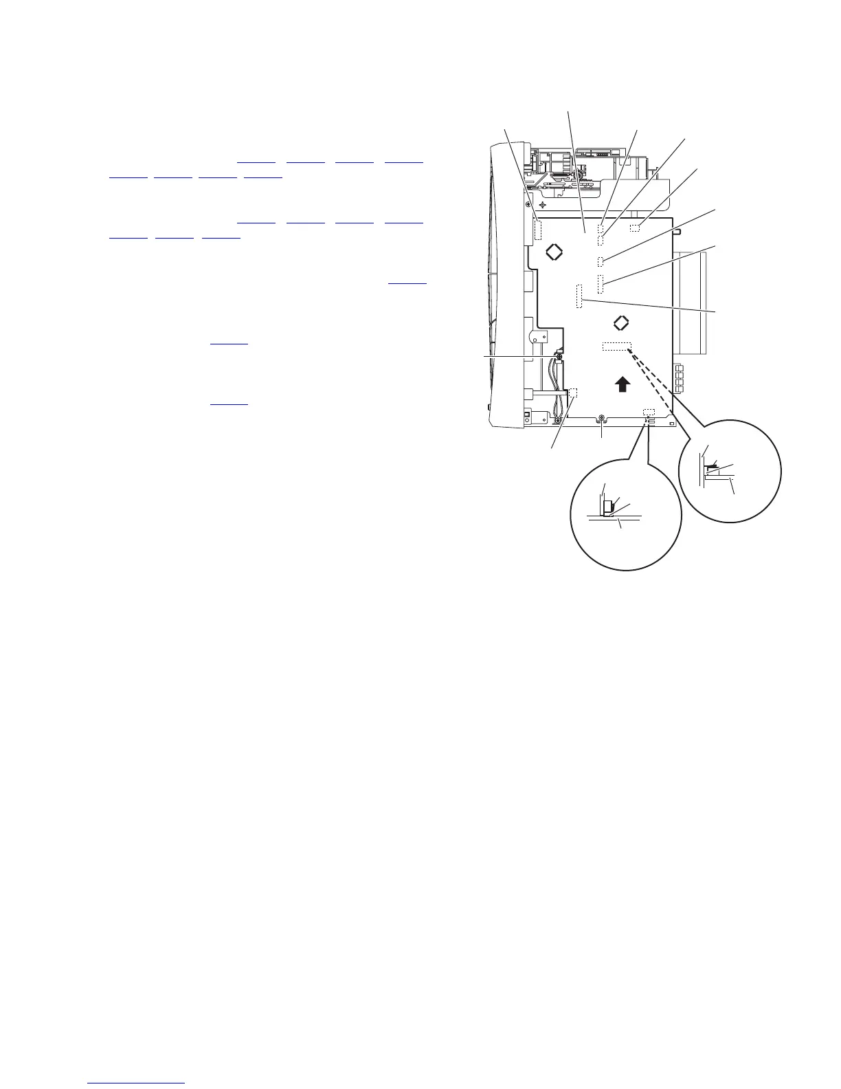
(See Fig.16)
• Remove the metal cover, tuner, fan and rear panel.
(1) From the right side of the main body, remove the screw L
and screw M attaching the main board.
(2) From the inside of the main body, disconnect the card wires
from the connectors (CN720
, CN730, CN740, CN760,
CN800, CN810, CN820, CN830) on the forward side of the
main board. [For DX-T9, DX-T7]
(3) From the inside of the main body, disconnect the card wires
from the connectors (CN720
, CN730, CN740, CN760,
CN800
, CN820, CN830) on the forward side of the main
board. [For DX-T5]
(4) Disconnect the main board from the bridge board toward
this side while releasing the claw h of the connector CN850
on the main board.
(5) Disconnect the main board from the surround terminal
board in the direction of the arrow while releasing the claw
i of the connector CN970
on the surround terminal board.
[For DX-T7]
(6) Disconnect the main board from the surround terminal
board in the direction of the arrow while releasing the claw
i of the connector CN990
on the surround terminal board.
[For DX-T9]
Note:
When releasing the claws (h, i), take care not to break them.
Fig.16
CN720
CN810
CN800
CN760
CN820
CN830
CN730
Main board
CN740
M
L
Main board
CN970
(CN990)
i
Main board
Bridge board
CN850
h
Surround
terminal board