1-20 (No.MB368)
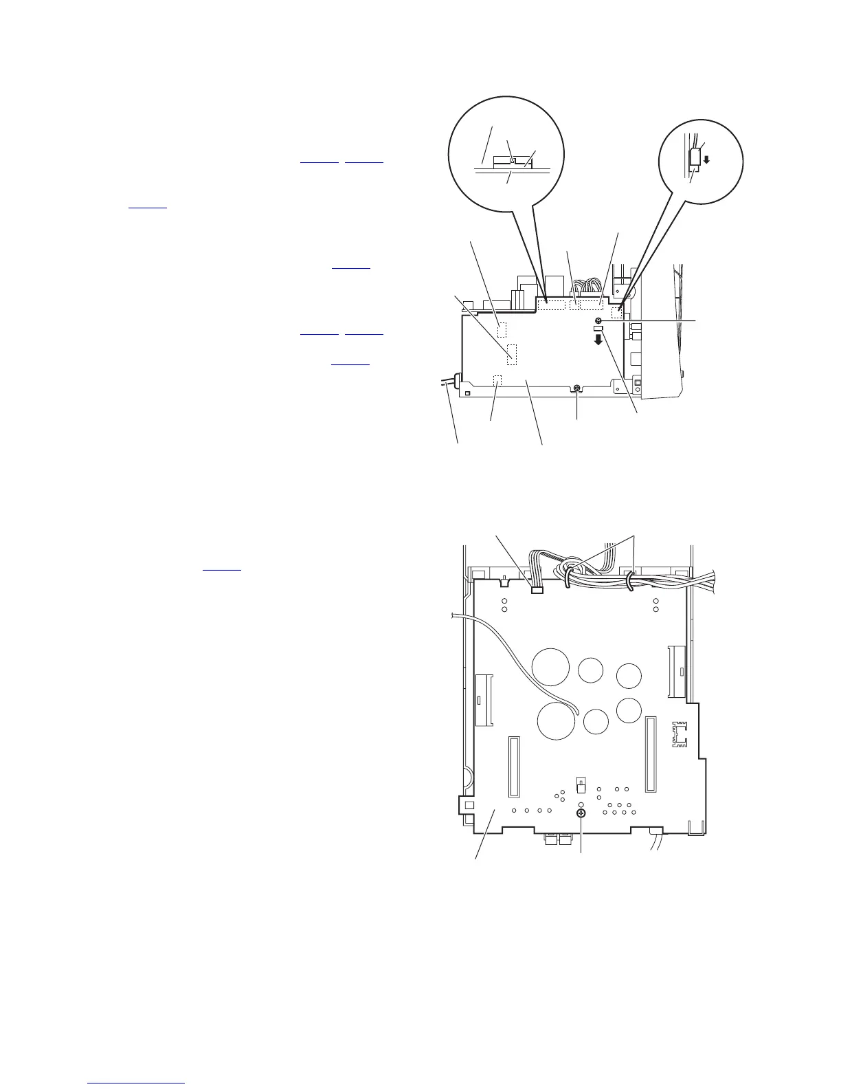
3.1.12 Removing the primary board
(See Fig.20)
• Remove the metal cover, tuner, fan, rear panel, main board,
amplifier 1 board and amplifier 2 board.
(1) From the left side of the main body, remove the screw Q
and screw R attaching the primary board.
(2) Disconnect the wires from the connectors (CN103
, CN106)
on the primary board.
(3) Disconnect the parallel wire while releasing the lock of the
connector CN105
on the primary board in the direction of
the arrow.
(4) Release the claw m in thr direction of the arrow and discon-
nect the primary board from the bridge board toward this
side while releasing the claw n of the connector CN104
on
the primary board.
Note:
When releasing the claw n, take care not to break it.
(5) Disconnect the wires from the connectors (CN101
, CN102)
on the forward side of the primary board.
(6) Disconnect the power cord from the connector CN100
on
the primary board.
(7) Take out the primary board from the main body.
Fig.20
3.1.13 Removing the bridge board
(See Fig.21)
• Remove the metal cover, tuner, fan, rear panel, main board,
amplifier 1 board, amplifier 2 board and primary board.
(1) From the top side of the main body, disconnect the parallel
wire from the connector CN202
on the bridge board.
(2) Remove the wire holders bundling the wires.
Reference:
After reassembling, bundle the wires with the wire hold-
ers as before.
(3) Remove the screw S attaching the bridge board.
(4) Take out the bridge board from the main body.
Fig.21
CN103
CN106
CN102
CN104
CN101
CN100
Primary board
Power cord
R
Q
n
Primary board
Bridge board
CN105
Lock
m
CN202 Wire holders
Bridge board S