1-12 (No.YD091)
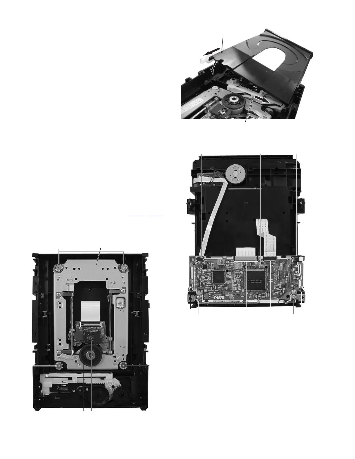
3.2.2 Reassembly the tray (See figure 5)
(1) The slide cam is done in the slide in the direction of the ar-
row.
(2) The shaft guide is done in the slide in the direction in the
back.
(3) The left side of the tray is inserted in the rail of the loading
base, and the shaft guide is built in.
(4) Please push the tray, and confirm whether the tray is nor-
mally good to the close position at the slide by manual.
Fig.5
3.2.3 Remove the traverse mechanism assembly (See figure 6, figure 7)
• Prior to performing the following procedure, remove the top
cover, tray.
(1) Disconnect the FFC wire from connector on the pick-up
unit.
ATTENTION:
The laser diode of "pick-up" might be destroyed by static
electricity. Please work after installing the wristband. In
addition, please do not touch in each part, the terminal,
and the laser diode terminal on the substrate of the pick-
up unit. Never
(2) Disconnect the FFC wire from connector CN103
, CN104
on the servo control board.
(3) Remove the four screws C attaching the traverse mecha-
nism assembly.
Fig.6
Fig.7
Slide cam
Shaft guide
C
C
C
Traverse mechanism assembly
Pick-up unitConnector
CN102
CN103
CN104
CN105
Hook d Hook d
Servo control board
D D