(No.YD091)1-27
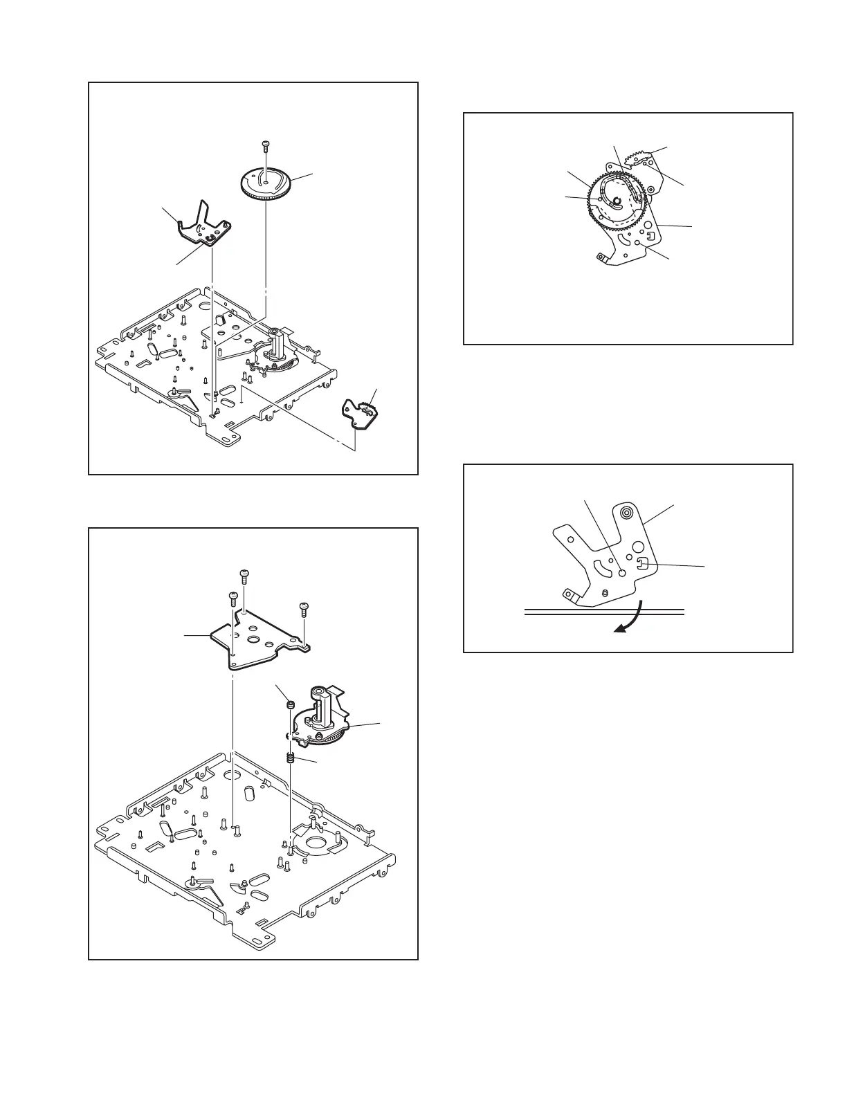
14. [38] Sub cam / [39] Arm gear 2 assembly / [40] Clutch lock lever assembly
Fig.4-5-14
15. [41] Capstan motor / [42] Drum base deck
Fig.4-5-15
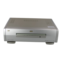
Note 14a:
How to attach the sub cam [38].
Fig.4-5-14a
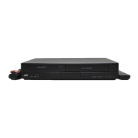
Note 14b:
How to remove the clutch lock lever assembly [40] L19
is located behind the mechanism assembly when the
phase is aligned correctly. The clutch lock lever assem-
bly can be removed by displacing it in the direction of
the arrow.
Fig.4-5-14b
31
(
S2
)
(
L19
)
<Note14a>
<Note14a>
<Note14a>
<Note14b>
[
38
]
[
40
]
[
39
]
32
(
S2
)
33
(
S2
)
34
(
S2
)
(
P7
)
Adjust nut
[
42
]
[
41
]
Phase alignment
Phase alignment
Phase alignment
Boss
[
38
]
[
39
]
[
40
]
Align the phases of the arm gear 2 assembly
[
39
]
and
clutch lock lever assembly
[
40
]
,then attach them by fitting
the boss into the lower cam slot and tighiten the screws.
(L19)
Phase alignment
[
40
]