1-26 (No.YD091)
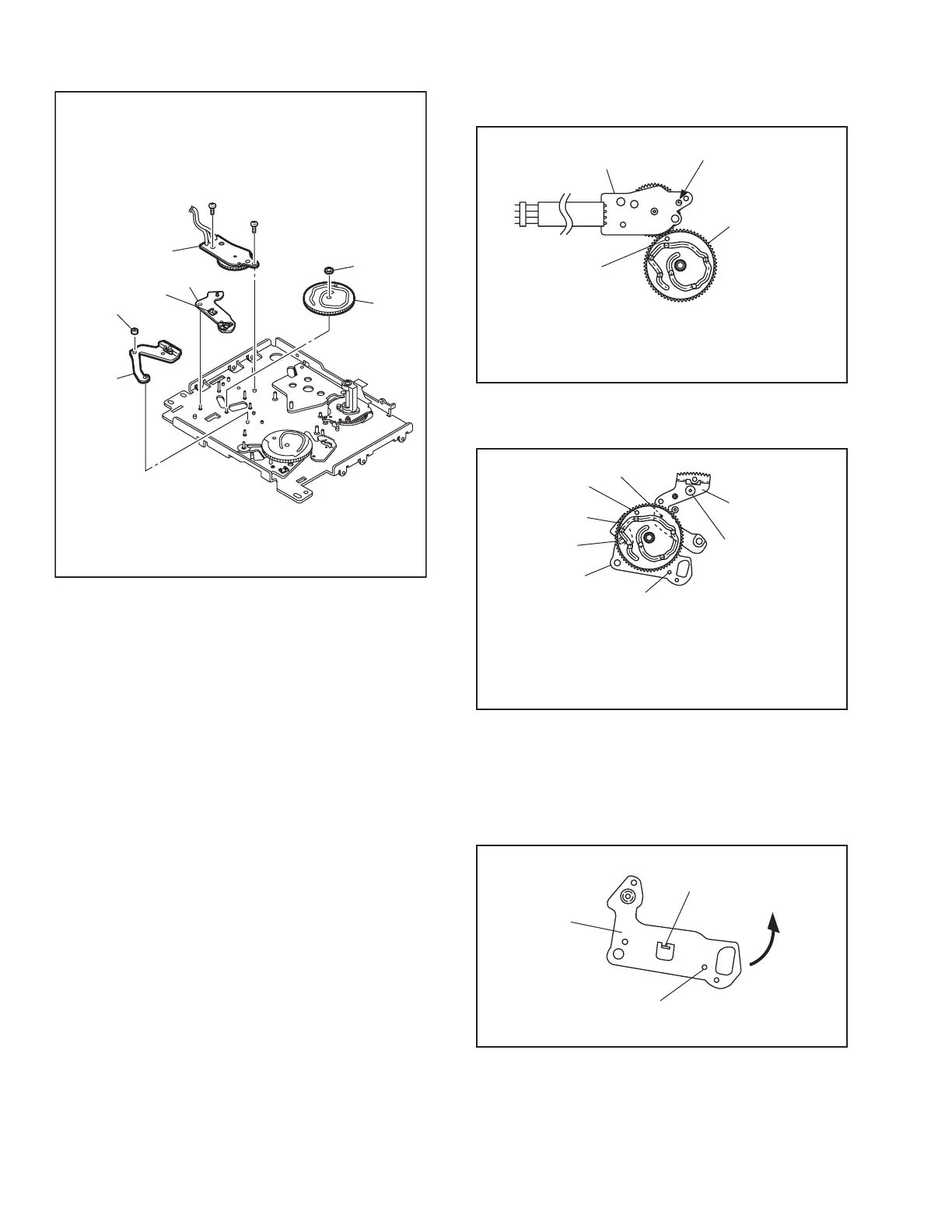
13. [34] Rotary encoder assembly / [35] Main cam / [36] Arm gear 1 assembly / [37] Centering arm assembly
Fig.4-5-13
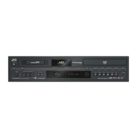
Note 13a:
How to attach the rotary encoder assembly [34].
Fig.4-5-13a
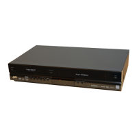
Note 13b:
How to attach the main cam [35] .
Fig.4-5-13b
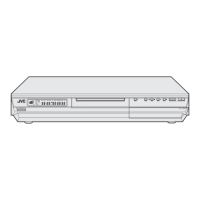
Note 13c:
How to remove the centering arm assembly [37] The
center arm assembly is located behind the mechanism
assembly when the phase is aligned correctly. The cen-
ter arm assembly can be removed by displacing it in the
direction of the arrow.
Fig.4-5-13c
30
(
S2
)
(
L18
)
(
W1
)
29
(
S2
)
<Note13a>
<Note13b>
<Note13c>
<Note13b>
<Note13b>
Collar
[
34
]
[
37
]
[
36
]
[
35
]
Phase alignment
Mark (colored : red)
[
34
]
[
35
]
Align the phase of the main cam
[
35
]
,then attach it by
placing the (red) coloured markings (on 2 gear teeth)
within the encircled area.
Phase alignment
Phase alignment
Phase alignment
Boss
Boss
[
36
]
[
35
]
[
37
]
Align the phases of the arm gear 1 assembly
[
36
]
and
centering arm assembly
[
37
]
,then attach the arm gear 1
assembly
[
36
]
/centering arm assembly
[
37
]
by fitting the
bosses into the lower cam slot,and fit the slit washer.
Phase alignment
(L18)
[
37
]