(No.YD125<Rev.001>)1-5
SECTION 2
SPECIFIC SERVICE INSTRUCTIONS
This service manual does not describe SPECIFIC SERVICE INSTRUCTIONS.
SECTION 3
DISASSEMBLY
Before disassembly, be sure to turn OFF the power and unplug
the power cord.
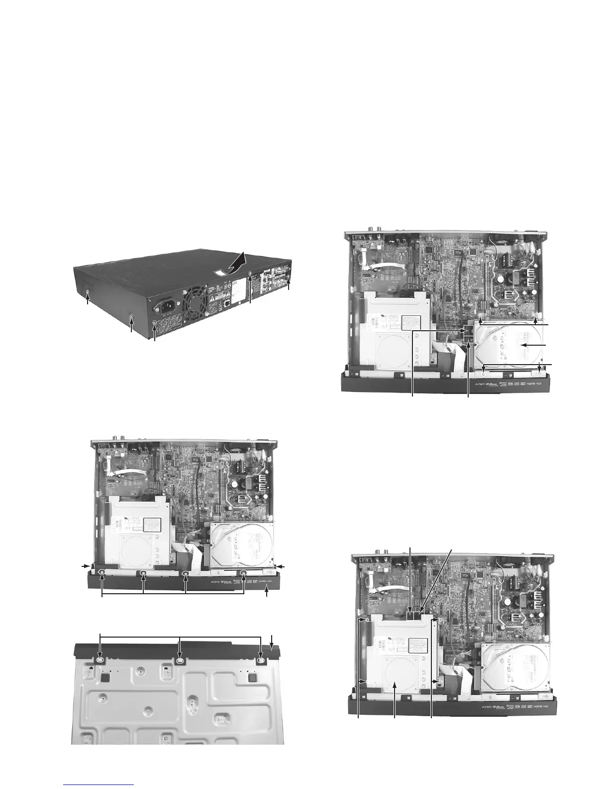
3.1 Removing the top cover (See Figure 1)
(1) Remove the four screws A attaching the top cover from
both sides.
(2) Remove the three screws B attaching the top cover from
the back.
(3) Remove the top cover by sliding it backward.
Fig.1
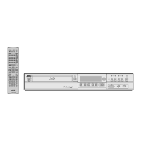
3.2 Removing the front panel assembly (See Figure 2 and
Figure 3)
• Remove the top cover.
(1) Remove the nine tabs on the front panel assembly, and
then remove the front panel assembly.
Fig.2
Fig.3
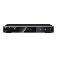
3.3 Removing the HDD (See Figure 4)
• Remove the top cover.
(1) Pull out the SATA cable and the HDD power cable con-
nected to the HDD.
(2) Remove the four screws C attaching the HDD bracket.
(3) HDD is removed from the HDD bracket.
Fig.4
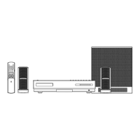
3.4 Removing the BD drive unit (See Figure 5)
• Remove the top cover.
(1) Pull out the SATA cable and the BD drive power cable con-
nected to the BD drive unit.
(2) Remove the four screws D attaching the drive bracket.
(3) The rear side of the BD drive unit is lifted a little and re-
moved.
(4) Drive bracket is removed from the BD drive unit.
Fig.5
A x 2
A x 2
B
B
B
Top cover
Top cover
Tab
Tab
Tab
Front panel assembly
Front panel assembly
Tab
C
HDD
C
HDD Power cable
SATA Cable
DD
BD Drive unit
BD Drive power cable
SATA Cable