2-37
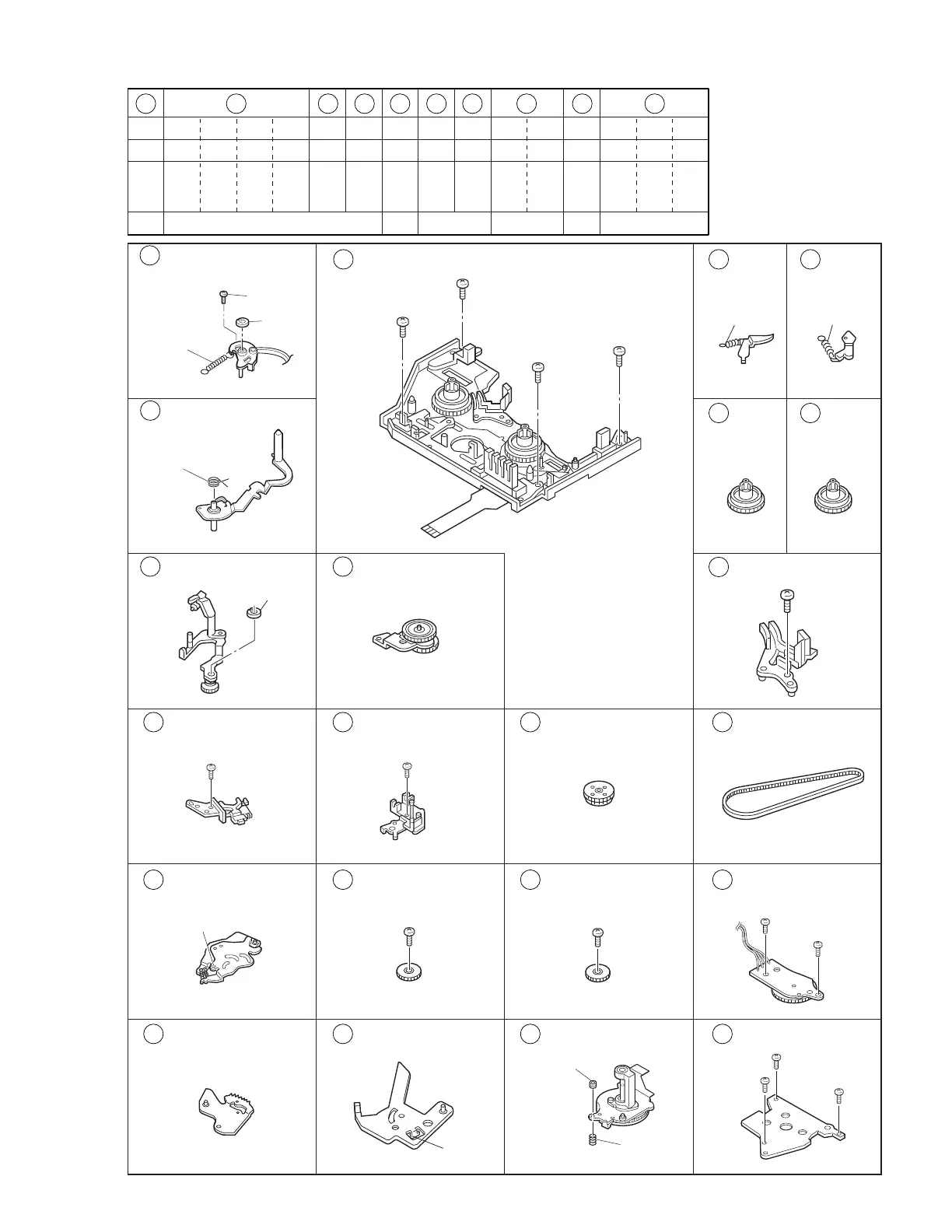
7 Band arm plate sub
assembly
S3, P2, L9, W2
P3
W1
P4, L10 P5, L11
S2
S2×2
S2, L14×2 S2
L17 S2 S2
L19 S2×3ADJUST NUT, P7
11 Sub deck assembly
S2×4
16 18 19 20 21 32 33 34 38 42
19 20 21 22 23 24 25 26 27 28 29 30 31 32 33 34
S2 S2 S2 S2 S2 S2 S2 S2 S2
2-13-7 2-13-9
2-13-14
2-13-12 2-13-13 2-13-152-13-8
S2 S2 S2 S2 S2 S2 S2
20 Base plate assembly
8 Tension arm sub
assembly
9
EXIT guide arm assembly
10 Swing arm assembly
21 Ent. guide base
assembly
22 Worm wheel 2 23 Timing belt
31 Charge arm assembly 32 Connect gear 2 33 Connect gear 2 34 Rotaly encoder
assembly
39 Arm gear 2 assembly 40 Clutch lock lever
assembly
41 Capstan motor 42 Drum base deck
12
Main
Brake(Sup)
assembly
13
Main
Brake(Take up)
assembly
14
Reel disk
assembly
(Sup)
16 Prism
15
Reel disk
assembly
(Take up)
25
(
S2
)
26
(
S2
)
(
L17
)
27
(
S2
)
28
(
S2
)
18
(
S2
)
15
(
S2
)
16
(
S2
)
17
(
S2
)
(
P5
)
(
P4
)
(
W1
)
(
W2
)
14
(
S3
)
(
P2
)
19
(
S2
)
(
L19
)
ADJUST NUT
(
P7
)
29
(
S2
)
30
(
S2
)
33
(
S2
)
32
(
S2
)
34
(
S2
)
(
P3
)
Fig. 2-11-1B