3-1
SECTION 3
ELECTRICAL ADJUSTMENT (VHS)
3.1 Precaution
The following adjustment procedures are not only necessary
after replacement of consumable mechanical parts or board
assemblies, but are also provided as references to be re-
ferred to when servicing the electrical circuitry.
In case of trouble with the electrical circuitry, always begin a
service by identifying the defective points by using the meas-
uring instruments as described in the following electrical ad-
justment procedures. After this, proceed to the repair, replace-
ment and/or adjustment. If the required measuring instruments
are not available in the field, do not change the adjustment
parts (variable resistor, etc.) carelessly.
3.1.1 Required test equipments
• Color (colour) television or monitor
• Oscilloscope:
wide-band, dual-trace, triggered delayed sweep
• Frequency counter
• Audio level meter
• Signal generator: RF / IF sweep / marker
• Signal generator: stairstep, color (colour) bar [NTSC]
• Recording tape (VHS/SVHS)
• Digit-key remote controller (provided)
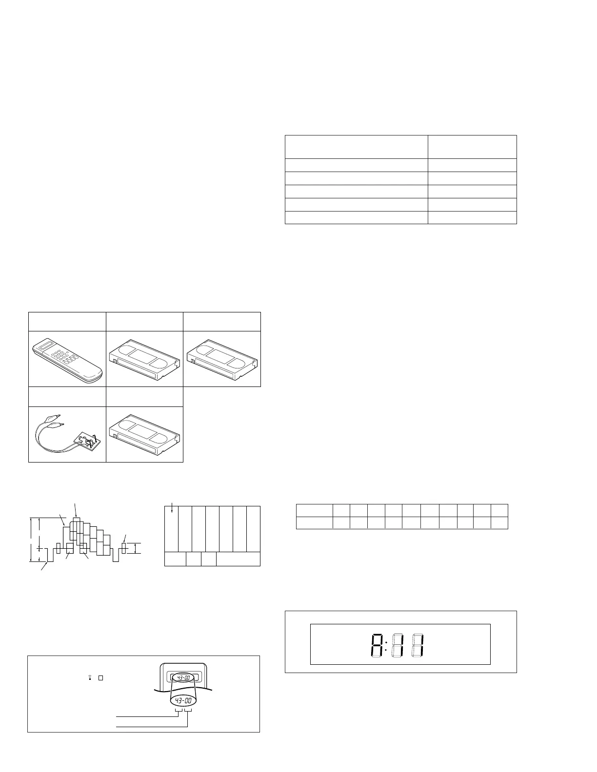
3.1.2 Required adjustment tools
3.1.3
Color (colour) bar signal,Color (colour) bar pattern
3.1.4 Switch settings and standard precautions
The SW settings of the VCR and the standard precautions
for the electrical adjustments are as follows.
•
When using the Jig RCU, it is required to set the VCR to
the Jig RCU mode (the mode in which codes from the Jig
RCU can be received). (See SECTION 1 DISASSEMBLY.)
Jig RCU
PTU94023B
Alignment tape
(SP, stairstep, NTSC)
MHP
Alignment tape
(EP, stairstep, NTSC)
MHP-L
LPF
PTU93006
Alignment tape
(S-VHS, SP/EP, color (colour) bar)
MH-1H
3.1.5 EVR Adjustment
Some of the electrical adjustments require the adjustment
performed by the EVR system. The main unit have EEPROMs
for storing the EVR adjustment data and user setups.
Notes:
• In the EVR adjustment mode, the value is varied with
the channel buttons (+, –). The adjusted data is stored
when the setting mode changes (from PB to STOP,
when the tape speed is changed, etc.). Take care to
identify the current mode of each adjustment item
when making an adjustment.
• When changing the address setting in the EVR adjust-
ment mode, use the Jig RCU or the remote controller
having numeric keypad with which a numeric code can
be directly input.
The remote control code of the Jig RCU corresponds
to each of the digit keys on the remote controller as
follows.
• As the counter indication and remaining tape indica-
tion are not displayed FDP during the EVR adjustment
mode, check them on the TV monitor screen.
• When performing the EVR adjustment, confirm that the
FDP indication is changed to the EVR mode, as shown
below.
Digit-key 0 1 2 3 4 5 6 7 8 9
Code 20 21 22 23 24 25 26 27 28 29
•
Set the switches as shown below unless otherwise
specified on the relevant adjustment chart. The switches
that are not listed below can be set as desired.
If the VCR is not equipped with the functions detailed
below, setup is not required.
• If there is a reference to a signal input methed in the
signal column of the adjustment chart, “Ext. S-input”
means the Y/C separated video signal and “Ext. input”
means the composite video signal input.
• Unless otherwise specified, all measuring points and
adjustment parts are located on the Main board.
INITIAL MODE
DATA CODE
CUSTOM CODE
43: A CODE
[Data transmitting method]
Depress the “ ” ( 3 ) button
after the data code is set.
Jig RCU
AUTO PICTURE/VIDEO CALIBRATION/
OFF
B.E.S.T./D.S.P.C.
PICTURE CONTROL/SMART PICTURE
NORMAL/NATURAL
VIDEO STABILIZER OFF
TBC ON
Digital 3R ON
VIDEO NAVIGATION/TAPE MANAGER
OFF
Fig. 3-1-4a Jig RCU [PTU94023B]
Fig. 3-1-5a EVR mode
White(75%)
100 IRE
40 IRE
Horizontal sync
QI
1V
White(100%)
Yellow
Cyan
Green
Magenta
Red
Blue
Burst
40 IRE
White
Yellow
Cyan
Green
Magenta
Red
Blue
Q I Black
White
100%
(75%)
•
Color(colour) bar signal [NTSC]
•
Color(colour) bar pattern [NTSC]