4-28
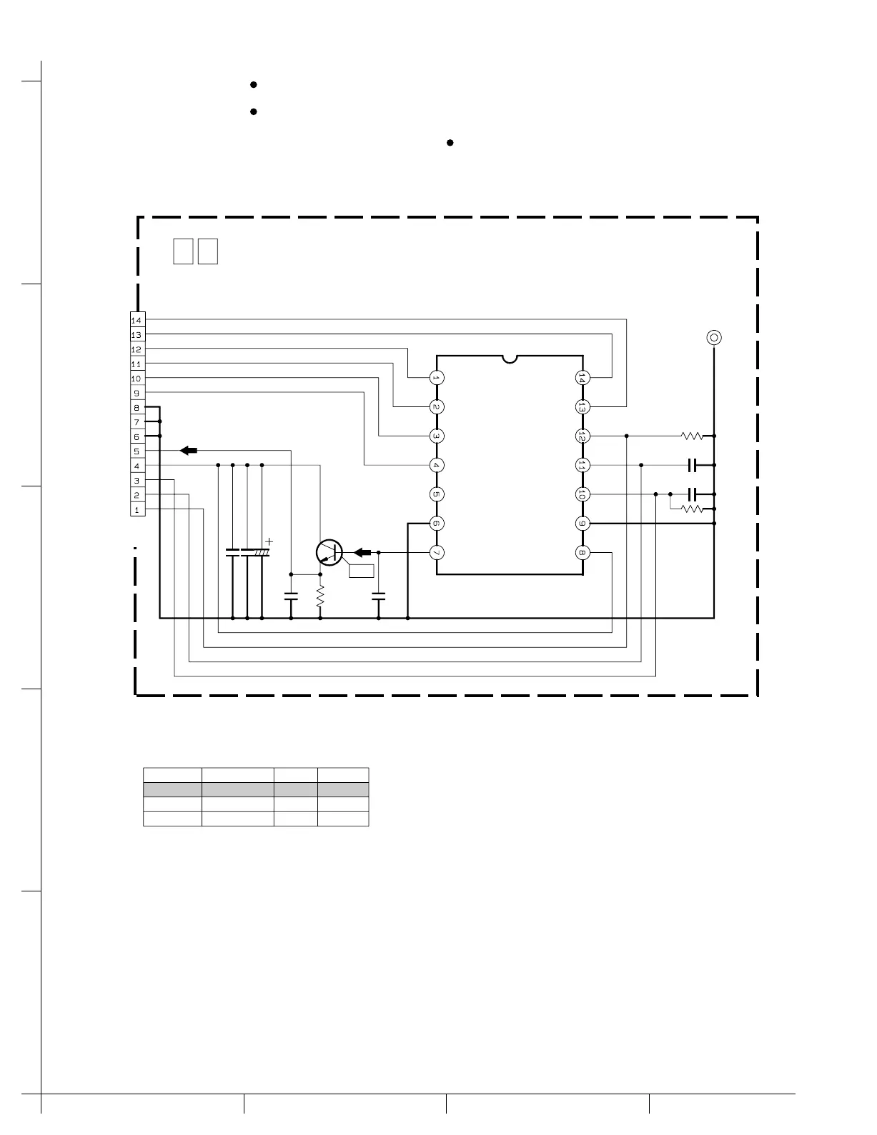
4.14 CCD SCHEMATIC DIAGRAM
5
4
3
2
1
DCBA
When ordering parts
,
be sure to order according to the Part Number indicated in the Parts List.
IC5301 is incorporated in the CCD base assembly.
When IC5301 needs replacement
,
replace the CCD
For the destination of each signal and further line connections that are cut off from
this diagram
,
refer to "4.1 BOARD INTERCONNECTIONS".
NOTES :
base assembly in whole because it cannot be re-
placed alone.
CCD
CCD
IC5301
CN5301
C5307
Q5301
R5302
C5302
C5303
R5301
C5301
C5304
CL5301
R5304
C5305C5306
5.6k
1.5
1500p
1MΩ
0.1
0.1
27p
VO
V4
V3
V2
V1
NC
GND GND
VDD
SUB
VL
RG
H1
H2
H1
H2
V4
V3
V2
V1
GND
GND
GND
CCD_OUT
CCD_HV
SUB
CCD_LV
RG
QGF0505F1-14X
2SC3931/CD/-X
/25
#
T
MODEL IC5301 CCD_HV CCD_LV
15V
15V
-8V
-7.5V
MN39117FT
ICX297AKA-L
NTSC_L
PAL_L
NOTES : 1. The parts with marked ( ) is not used.
2. For CCD waveform, please refer to page 4-45.
y40082001a_rev0
TO TG/CDS
CN22
0 2 CCD
WF1
∗
∗
∗
∗