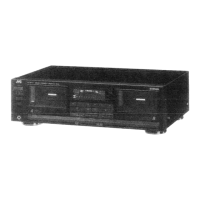
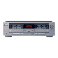
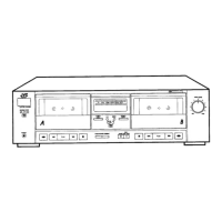
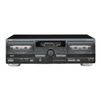
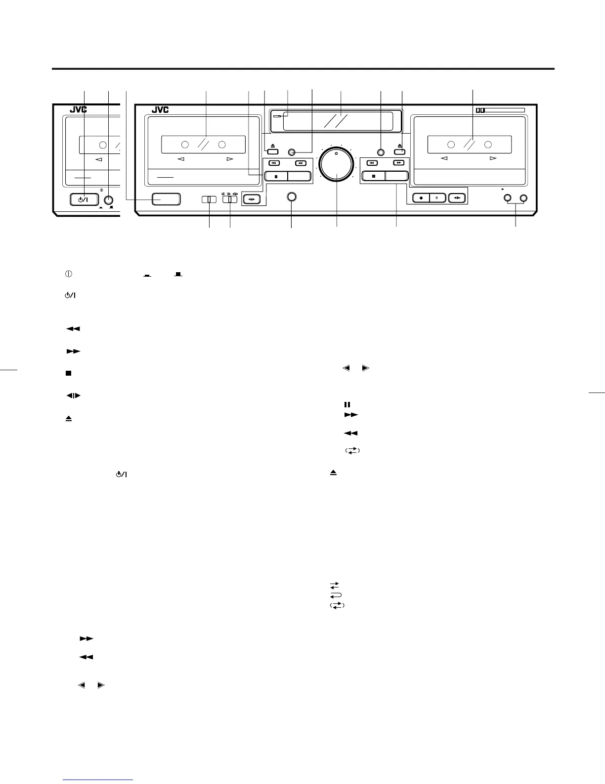
NAMES OF PARTS AND THEIR FUNCTIONS
1 POWER switch ( ON OFF) (B version)
POWER switch (On/Standby) (J version)
2
switch (STANDBY/ON) (B version)
3 Cassette holder (deck A)
4 Cassette operation buttons (deck A)
: Press to wind the tape quickly from right
to left.
: Press to wind the tape quickly from left to
right.
(stop) : Press to stop the tape.
PLAY : Press to play the tape.
direction : Press to change the direction of tape
travel.
5
(eject) button (deck A)
6 Power STANDBY indicator
Lights when in the power standby mode.
7 COUNTER RESET button (deck A)
Press this button to set the digital counter to ‘‘00 00’’.
Even if the
(STANDBY/ON) is set to STANDBY, the
counter value at that time is stored in memory.
8 Indicators
1 DDRP indicator
2 Peak level indicator
These indicators light according to the level of the signal
being recorded or the level of the signal recorded on the
tape.
Note:
0 dB : IEC (DIN) STANDARD LEVEL (250 nWb/m)
0 VU : Signal level at 160 nWb/m
3 HX PRO indicator
4 Digital counter
The counter reading increases while the tape is running
from left to right and decreases when it is running from
right to left.
5 Mechanism mode indicators (Deck A)
: This lights when winding the tape
from left to right.
: This lights when winding the tape
from right to left.
PLAY : This lights when in the playback.
, : Indicates the direction of tape travel.
6 Dubbing mode indicators
‘‘DUBBING >’’ : Lights when in the normal-speed dub-
bing mode.
‘‘DUBBING >>’’ : Lights when in the high-speed dub-
bing mode.
7 CONT : Lights when the unit is in the continu-
ous play mode.
8 Mechanism mode indicators (Deck B)
PLAY : Lights when the unit is in the playback
and record modes.
, : Indicates the direction of tape travel.
REC : Lights when the unit is in the record
and record-pause modes; blinks dur-
ing record muting.
: Pause indicator
: This lights when winding the tape
from left to right.
: This lights when winding the tape
from right to left.
9
: Indicates reverse mode.
9 COUNTER RESET button (deck B)
0
(eject) button (deck B)
q Cassette holder (deck B)
w DOLBY NR switch
Set to B or C for recording using the Dolby NR system or for
playing back a tape that was recorded using the Dolby NR
system.
Set to OFF when the Dolby NR system is not used.
e REVERSE MODE switch
Select the single side or full record/playback mode, or the
continuous play mode.
: For single-side recording or playback.
: To play or record both sides A and B.
: To play sides A and B continuously.
r PHONES jack
Connects headphones (with an impedance of 8 Ω to1kΩ).
12
STANDBY / ON
POWER
REC/REC MUTE
PAUSE
COUNTER RESET
COUNTER RESET
PHONES
A B SYNCHRO DUBBING
NORM SPEED HIGH SPEED
PLAY
PLAY
MIN
MAX
1
2
5
3
4
6
INPUT LEVEL
MIN
MAX
1
2
5
3
4
6
7
8
9
INPUT LEVEL
TD-W254
ON
OFF
DOUBLE CASSETTE DECK
DOLBY B-C NR HX PRO
AUTO TAPE SELECTOR / CONTINUOUS PLAY
DOLBY B NR
REVERSE MODE
OFF C
B
B
REC/PLAYBACK
3MOTOR SILENT MECHANISM
AUTO REVERSE
3MOTOR SILENT MECHANISM
A
PLAYBACK
AUTO REVERSE
COMPULINK
Component
STANDBY
3456
7
890 q
uy
e
t
r
1
POWER
REC/REC MUTE
PAUSE
COUNTER RESET
COUNTER RESET
PHONES
A B SYNCHRO DUBBING
NORM SPEED HIGH SPEED
PLAY
PLAY
MIN
MAX
1
2
5
3
4
6
INPUT LEVEL
MIN
MAX
1
2
5
3
4
6
7
8
9
INPUT LEVEL
TD-W254
DOUBLE CASSETTE DECK
DOLBY B-C NR HX PRO
AUTO TAPE SELECTOR / CONTINUOUS PLAY
DOLBY B NR
OFF C
B
B
REC/PLAYBACK
3MOTOR SILENT MECHANISM
AUTO REVERSE
3MOTOR SILENT MECHANISM
A
PLAYBACK
AUTO REVERSE
COMPULINK
Component
REVERSE MODE
w
STANDBY
(B version) (J version)
–6–
id8/i10371/ 09/23/99 Page 6
 Loading...