EasyManuals Logo

JVC TH-A35 Service Manual

JVC TH-A35
22 pages
To Next Page IconTo Next Page
To Previous Page IconTo Previous Page
Page #7 background imageLoading...
Page #7 background image
TH-A35
1-7
Fig.3
Fig.4
Fig.5
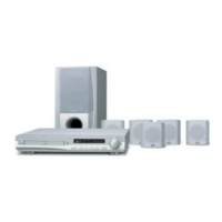
Removing the cabinet front
(See Fig.3)
[Caution] You must ensure the TRAY door isn't it's place
before you remove the panel front from body.
1. Unscrew the serew 2 C & 2 D.
2. Pull the panel front toward yourself while pressing 5
stoppers to disengage.
Removing the TUNER and panel rear
(See Fig.4)
1. Unserew the screw H form mpeg board unit and unit
and main board unit.
2. Unserw the screw K form body.
3. Take the supply cord out of panel rear.
4. Remove teh panel rear with tuner .
< CHAS, MAIN ASSEMBLY >
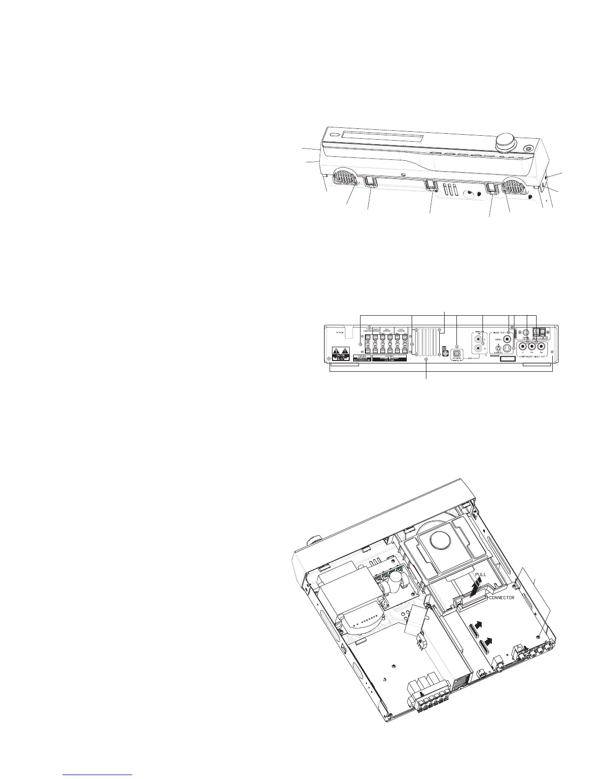
Removing the MPEG BOARD
(See Fig.5)
[Caution] Mpeg board may be taken out only when the
panel rear and Tunet have been taken away.
1. Pull the cable connetor mpeg board.
2. Unscrew the screw M.
3.Separate the mpeg board from main board
vertically.
D
C
STOPPER
STOPPER
STOPPER
STOPPER
STOPPER
C
D
M
CLASS 1
LASER PRODUCT
H
K

Other manuals for JVC TH-A35

Questions and Answers:

Question and Answer IconNeed help?

Do you have a question about the JVC TH-A35 and is the answer not in the manual?

JVC TH-A35 Specifications

Amplifier Section IconAmplifier Section
power per channel45 watts
impedance6 ohms
frequency1 kHz
Subwoofer IconSubwoofer
woofer size16 cm
sustained power capacity100 W
impedance10 Ω
Audio Section IconAudio Section
weight4.8 kg
frequency range25 Hz to 200 Hz
dimensions202 mm × 330 mm × 341 mm
Video Section IconVideo Section
dimensions92 mm × 97.5 mm × 92 mm
weight650 g
frequency range90 Hz to 20 kHz
Tuner Section IconTuner Section
FM tuning range87.50 MHz – 108.00 MHz
AM tuning range522 kHz – 1 629 kHz
power supply230 V, 50 Hz

Related product manuals