(No.MB618)1-11
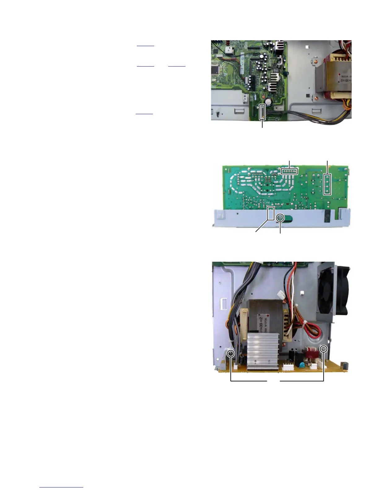
3.1.7 Removing the POWER BOARD assembly (See Fig.10 to 12)
(1) Disconnect the connector wire from POWER BOARD as-
sembly connected to connector CN151
of the MAIN
BOARD assembly. (See Fig.10)
(2) Disconnect the connector wires from POWER TRANS-
FORMER connected to connector CN102
and CN103 of
the POWER BOARD assembly. (See Fig.11)
(3) Remove the one screw R attaching the POWER BOARD
assembly. (See Fig.11)
(4) Remove the two screws S attaching the POWER BOARD
assembly. (See Fig.12)
(5) Disconnect the connector wire from POWER TRANS-
FORMER connected to connector CN104
of the POWER
BOARD assembly. (See Fig.11)
Fig.10
Fig.11
Fig.12
CN151
CN103
CN104
CN102
R
S