1-12 (No.MB393)
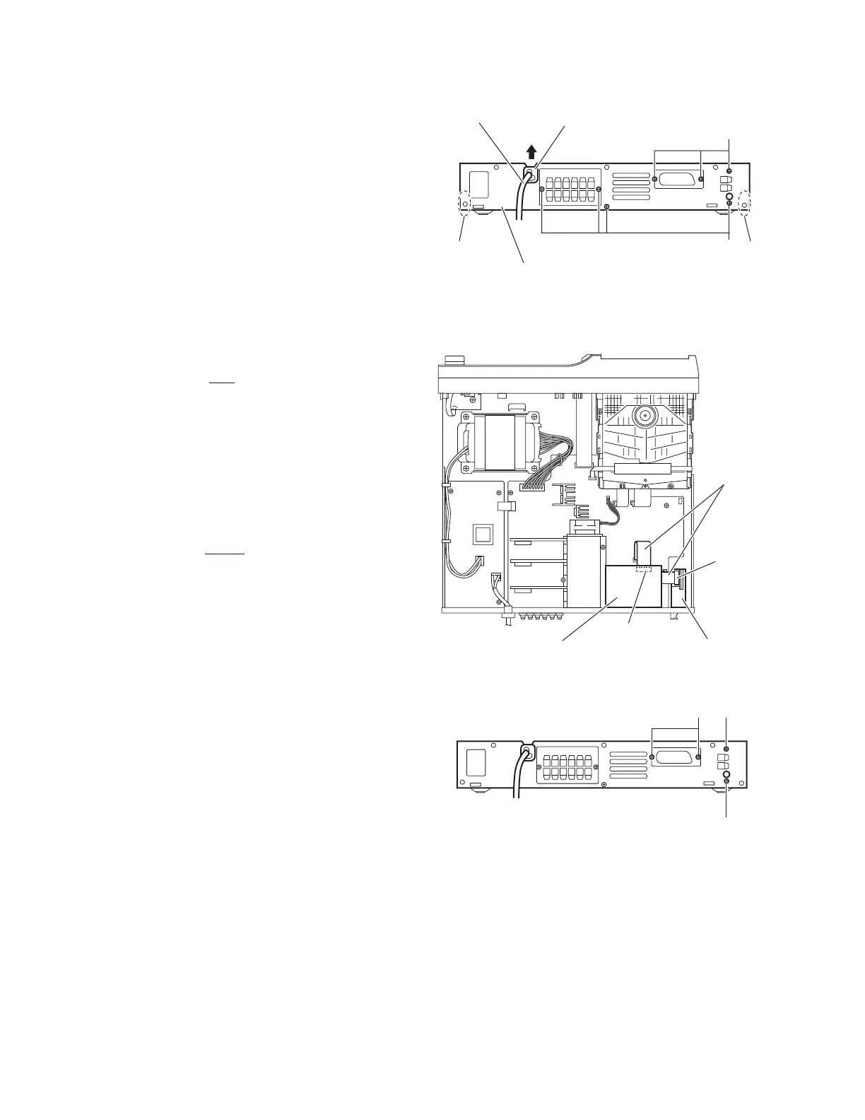
3.1.5 Removing the rear panel
(See Fig.9)
• Remove the metal cover.
(1) From the back side of the main body, remove the strain re-
lief attaching the power cord in the direction of the arrow.
(2) Remove the seven screws F attaching the rear panel to the
main body.
(3) Release the joints d, and remove the rear panel from the
main body.
Fig.9
3.1.6 Removing the tuner assembly
(See Figs.10 and 11)
• Remove the metal cover.
(1) From the top side of the main body, disconnect the card
wire from the connector CN1
on the tuner assembly. (See
Fig.10.)
(2) From the back side of the main body, remove the two
screws G attaching the tuner assembly to the rear panel.
(See Fig.11.)
(3) Take out the tuner assembly from the main body.
3.1.7 Removing the scart terminal board
(See Figs.10 and 11)
• Remove the metal cover.
(1) From the top side of the main body, disconnect the card
wire from the connector CN300
on the scart terminal board.
(See Fig.10.)
(2) From the back side of the main body, remove the two
screws H attaching the scart terminal board to the rear pan-
el. (See Fig.11.)
(3) Take out the scart terminal board from the main body.
Fig.10
Fig.11
Rear panel
F
F
Strain relief
Power cord
d d
Scart terminal board
Tuner assembly
CN300
CN1
Card wires
G
HG
 Loading...