11
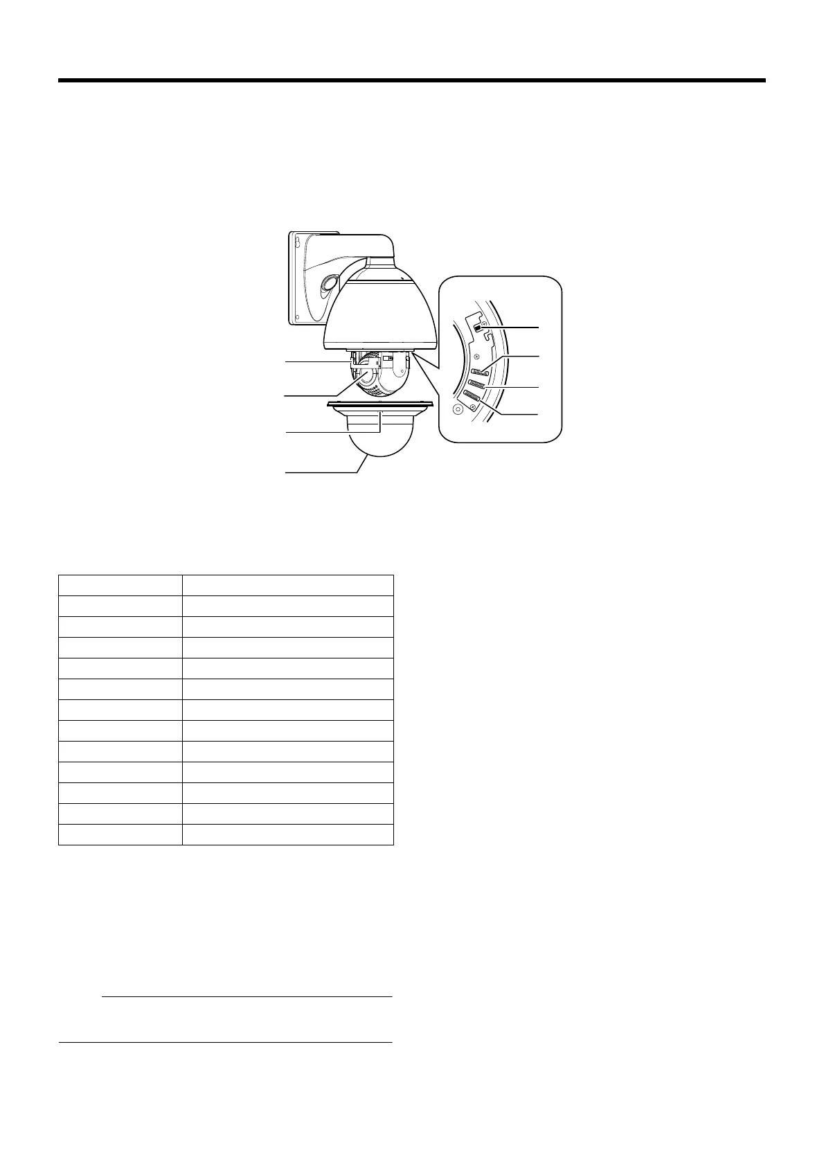
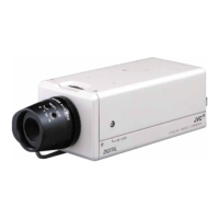
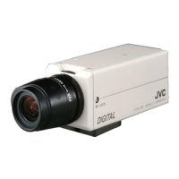
䡵 Camera (Interior)
I Alarm Input 2 to 6/Alarm Output 2 cable
This is a cable for alarm input 2 to 6 and alarm output 2.
(A Page 32)
J Front Mask
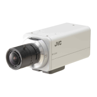
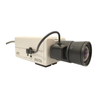
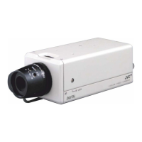
K Lens
Lens cannot be replaced.
L Dome Cover Fixing Screws (x4)
M Dome Cover
The dome cover is a delicate object. Handle it with care.
Note :
● It is covered with a protective sheet during shipment. Do
not remove this sheet until installation is complete.
N Option Switch
Configure this switch when Pelco protocol is used.
(A Page 19)
O Machine ID Setting Switch
When the communication system is RS-485 multi DROP
such as the RM-P2580 system, a machine ID will be set for
every camera. (A Page 31)
P Setting Switch
This switch allows you to configure settings such as protocol
and SYNC. (A Page 30)
Q Heater ON/OFF Switch
This is the ON/OFF switch for automatic control of the built-in
heater.
This product comes with a built-in heater to prevent the dome
cover from being covered with snow and frost as well as
fogging. When installing the heater at an unrequired location,
turn off the switch of the heater. Set the power of the heater
to AONB during use. (A Page 27)
Q
O
N
P
J
K
L
M
Cable color Signal Name
BROWN Alarm input 2
RED Alarm input 2 (COM)
ORANGE Alarm input 3
YELLOW Alarm input 3 (COM)
GREEN Alarm input 4
BLUE Alarm input 4 (COM)
PURPLE Alarm input 5
GRAY Alarm input 5 (COM)
WHITE Alarm input 6
BLACK Alarm input 6 (COM)
PINK Alarm output 2
LIGHT GREEN Alarm output 2 (COM)