No. 51961
TM-H1950CG
3
SAFETY PRECAUTIONS
1. The d esign of t his p rodu ct c ont ains spec ial h ardwar e, man y
circuit s a nd co mpon ent s sp ecially f or s afet y p urpos es. For
continued protection, no changes should be made to the
origina l des ign u nless a uthorized in writing by t he man uf actu rer.
Rep lacemen t parts must be id ent ic al t o t hos e u sed in the
origina l circuit s. Se rvic e sho uld be performed b y qualified
p ers onn el o nly.
2. Alte rations of th e desig n o r circu itry of th e p rodu cts s hould n ot
b e mad e. A ny de sign altera tions o r additio ns will void th e
manufacturer's warranty and will further relieve the
manu fact urer of r esp ons ib ilit y f or pe rs ona l in ju ry or p r opert y
d amage resu lt in g t her ef rom .
3. M an y e lectrical an d m echanic al pa rt s in the pr oducts h ave
sp ecial saf ety- relat ed c har act eris tics. Th ese charac teristics ar e
oft en n ot e vid ent from visu al inspe ction no r can t he prote ction
aff orde d by th em n ecess ar ily be o btained b y using
replac ement co mpon ent s rated for higher vo ltag e, wa ttag e, etc.
Rep lacemen t part s which have t he se sp ecial s afet y
ch aracteristics a re id entifie d in th e parts list of S ervice man ua l.
Electrical components having such features are identified
by shading on the schematics and by (!
!!
!) on the parts list
in Service manual . Th e u se of a su bst itu te re plac emen t which
does not have the same safet y characterist ics as the
reco mmen de d re plac emen t pa rt shown in the pa rts list of
Se rvice manual m ay c aus e sh ock, f ire, or o th er haz ards.
4. Use isola tion tr ansforme r when hot chass is .
The chassis and any sub-chassis contained in some products
are c on nect ed to on e side of the AC p ower line . An isola tion
tr ansf or mer of adequ ate cap acity sh ou ld be inser t ed bet ween
th e p rodu ct and t he AC p ower su pp ly p oint while p er form ing
an y service on so me pro ducts wh en th e HOT ch assis is
exp ose d.
5. Do n't short between the LIVE side ground and ISOLATED
(NEUTRAL) side ground or EARTH side ground when
repairing.
So me mod el's p ower c ircuit is part ly dif fer ent in t he GND. Th e
diff erenc e of t he GND is sh own by th e LI VE : (") side GND,
th e ISO LATED(NEUTRAL) : (
#
) side GND an d EARTH : (
$
)
side GND. Don 't sho rt be twee n t he LIVE sid e GND and
ISO LATE D(NEUTRAL) side GND or EARTH side GND a nd
never measure with a measuring apparatus (oscilloscope etc.)
th e LI VE side GND a nd ISO LATED(NEUTRA L) sid e GND or
EARTH sid e GND at the s ame time.
If above note will not be kept, a fuse or any parts will be broken.
6. If an y re pair h as b ee n mad e to the ch assis, it is recom mend ed
th at t he B1 se ttin g sh ou ld b e chec ked or ad juste d (S ee
ADJUSTMENT OF B 1 POWE R SUPPL Y).
7. The hig h volt age a pp lied t o th e pictu re tube mu st co nfo rm wit h
that specified in Service manual. Excessive high voltage can
cau se an incr ease in X-Ra y emission , a rcin g and p ossible
compo ne nt dam ag e, theref or e oper atio n un der excess ive high
voltage c ond it ions sh ou ld be ke pt to a minimum, or sh ou ld be
preve nt ed. I f seve re arc in g occu rs, remove th e AC p ower
immediately and determine the cause by visual inspection
(incor rect insta lla tion , crac ked o r m elte d high voltag e h arness,
p oor s olde rin g, etc. ). T o ma in ta in the prop er m inim um le vel of
soft X-Ray emission, components in the high voltage circuitry
includ ing the pictu re tube mu st be the exa ct r ep lacem en ts or
alte rn at ives a ppro ved b y th e manuf actur er of the comp lete
prod uct.
8. Do n ot c hec k high volta ge by d rawin g a n arc. Us e a high
voltage mete r or a h igh volt age p robe with a VTVM . Disch arge
th e p ictu re tu be bef ore a tte mpting me ter co nne ction , by
con nec ting a clip lead t o th e grou nd frame a nd con n ecting t he
oth er end of t he lead thr ough a 10 kΩ 2W resist or to t he ano de
bu tto n.
9. W hen se rvice is requ ired, ob serve the orig in al lea d dress.
Extra p recau tion sh ou ld be given t o assu re corre ct lea d dres s
in the h igh voltage c ircu it area . W here a sh ort cir cuit ha s
occu rre d, th ose c omp onents that ind ic ate eviden ce of
overheating should be replaced. Always use the
manu fact urer 's replace ment compon ents.
10 . Isolation Check
(Safety for Electrical Shock Hazard)
Af ter re- a ssembling th e prod uct , always pe rf orm an iso lation
ch eck on the expo sed meta l p arts of th e c abin et (ant en na
ter mina ls, vide o/aud io inpu t and out put t ermin als, Con trol
knobs, metal cabinet, screwheads, earphone jack, control
sh afts, etc.) to be sure the pr o duct is saf e t o op erat e with out
d anger of elect rica l shoc k.
(1) Dielectric Strength Test
The is olat io n b etwe en the AC pr ima ry circu it and all m eta l parts
exp ose d t o th e us er, part icu larly an y expo sed metal p art having
a re turn pat h to the ch assis sh ou ld withst and a volta ge of
11 00V AC (r .m .s.) f or a p eriod of on e sec ond .
(. . . . Withs tand a voltage of 1100V AC (r.m. s.) to an appliance
rate d up to 120V , a nd 3 00 0V AC (r .m. s.) t o an ap plianc e ra ted
200V or more, for a period of one second.)
This m eth od of test requ ires a t est equipm en t no t gene r ally
fou nd in t he service t rade.
(2) Leakage Current Check
Plug t he A C line c ord dir ect ly int o th e AC ou tlet ( do not u se a
lin e is olation tra nsf ormer dur ing t his che ck.). Using a "L eaka ge
Current Test er ", mea sur e t he lea kag e curr ent from each
exp ose d metal part of the ca bine t, p artic ularly an y expo sed
metal part having a return path to the chassis , to a known good
ea rt h gro und (wa ter p ipe, etc.). A ny lea kag e cur ren t m ust not
exce ed 0. 5mA AC (r .m. s.).
Howeve r, in t ropical a rea, this m ust no t exc eed 0 .2m A AC
(r.m.s. ).
"
""
"
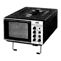
Alte rnate Che ck M ethod
Plug t he A C line c ord dir ect ly int o th e AC ou tlet ( do not u se a
line isolation transformer during this check.). Use an AC
voltmet er h aving 100 0 ohm s per volt or m ore sen sitivit y in the
follo win g manne r. Con nec t a 1 50 0Ω 1 0W resistor pa ra lle led
by a 0.15
μ
F AC- typ e cap acitor b etwe en an exp ose d meta l
p art an d a kno wn g o od earth grou nd (wate r pip e, et c.).
Measu re th e A C vo ltag e across th e resist or wit h t he AC
voltmeter. Move the res istor connection to each exposed metal
part, particularly any exposed metal part having a return path to
th e ch assis , and mea sur e t he A C volta ge across th e resisto r.
Now, r eve rs e th e plu g in t he A C out let a nd rep e at e ach
measu rem en t. An y volta ge me asu re d must not exce ed 0.7 5V
AC (r.m. s.). This corresp onds t o 0.5mA AC (r.m. s.).
Howeve r, in trop ic al area, this m ust n ot excee d 0 .3V AC
(r.m.s. ). This corresponds t o 0.2mA AC (r.m.s.).
0.15μF AC-T YPE
1500Ω 10W
GOOD
EARTH
GR OUND
PLACE THIS PROBE
ON E A CH EX PO SE D
ME T AL PA R T
AC VOLTMETER
(HAVING 1000 Ω/V,
OR MORE SENSIT IVITY)
11 . High voltage hold down circuit check.
Af ter r ep air of the high volt ag e hold d own cir cuit, th is circu it
sh all b e c hec ked to op erate corr ectly.
See ite m "Ho w to check the high voltage hold down
cir cuit".
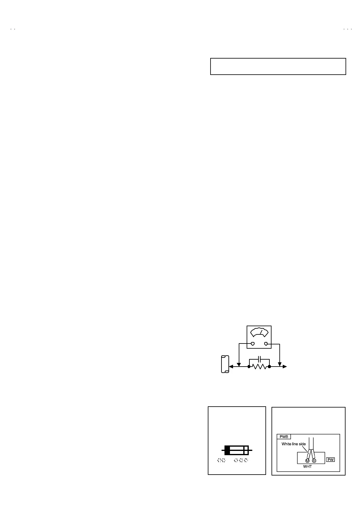
A V
This mark shows a fast
operating fuse, the
letters indicated below
show the rating.
POWER CORD
REPLACEMENT WARNING.
Co nne ct ing t he w hi te l ine side of pow er
cord to “WHT” chara cter side.
For District of power requirement is 120V AC
(Mainly North America)

 Loading...