No. 51961
TM-H1950CG
4
SAFETY PRECAUTIONS
1. The d esign of th is prod uct con tains sp ecial har dwa re , ma ny
circuit s and components specially for safety purposes. For
con tinu ed prot ection , no chan ges sh ould be made to the o rig inal
d esign un less a uth orized in writin g by the ma nufact urer.
Rep lacemen t par ts m ust b e id ent ic al to thos e u sed in th e origin al
circuit s. Se rvic e sh ou ld be pe rf ormed b y q ua lifie d perso nnel
on ly.
2. Alte rations of t he desig n or circuitry of t he pr oducts sh ould not be
made. Any design alterations or additions will void the
manu fact urer 's warra nt y and will f urther relieve t he ma nu factu rer
of r esp onsib ility for perso na l injury or p rop erty d am age r esult ing
th er efrom .
3. M any e lectrical an d mech anica l p arts in th e prod ucts have
special safety-related characteristics. These characteristics are
oft en no t e viden t f rom visua l insp ection n or ca n t he pr o tect io n
aff orde d by th em nece ssarily b e ob tain ed b y u sin g rep lacem ent
compo ne nts ra ted f or hig he r vo ltag e, watt ag e, etc. Rep lacemen t
p arts wh ic h ha ve these sp ecial s afet y ch aract erist ics are
identified in the parts list of S ervic e manual. El ec trical
components having such features are identified by shading
on t he sche matic s and by (
!
!!
!
) on the parts list in Service
manual. The us e of a substitu te replacemen t which do es n ot
h ave th e same saf ety ch aract erist ics as t he reco mmen de d
replac ement part sh own in th e p arts list of S ervice man ual may
cause shock, fire, or other hazards.
4. Do n't shor t between the LIVE side ground and ISOL ATED
(NEUTRAL) side ground or EARTH side ground when
repairing.
Some model's power circuit is partly different in the GND. The
diff erenc e of th e GND is sh own by t he LI VE : (
"
) side GND, the
ISO LATE D(NEUTRAL) : (#) side GND an d EA RTH : ($) side
GND. Don't short between the LIVE side GND and
ISO LATE D(NEUTRAL) side GND or EARTH sid e GND and
n ever mea sur e wit h a mea suring a ppa ratus (oscilloscop e etc.)
th e LI VE sid e GND an d IS OL ATED(NE UTRAL ) sid e GND or
EARTH sid e GND at the s ame time.
If above note will not be kept, a fuse or any parts will be broken.
5. If any repair has been made to the chassis, it is recommended
th at t he B1 set ting shou ld b e ch ecke d or adju ste d (Se e
ADJUSTMENT OF B 1 POWE R SUPPL Y).
6. The high volta ge app lie d t o th e pictur e tu be must con form wit h
th at sp ecified in S ervice m an ual. E xcessive h igh volt ag e ca n
cau se an incre ase in X- Ray emission , arcing an d possib le
component damage, therefore operation under excessive high
voltage conditions should be kept to a minimum, or should be
preve nt ed. If s evere arc in g occurs, remove t he AC power
immed iate ly an d de ter mine th e ca use b y visua l insp ect ion
(incor rect in stallat ion, cracke d or melte d high vo lt age harn ess,
p oor so ld ering, et c.). To maint ain the p rope r min imu m le vel of
sof t X-Ray emission, c omp on en ts in th e high voltag e circuitry
includ ing t he pict ure tu be must b e t he e xact rep laceme nts or
alte rn at ives ap prove d b y th e manuf act ur er of th e c omplet e
prod uct.
7. Do n ot c hec k high volt ag e b y drawing an arc. Use a high volt ag e
meter or a hig h v oltage probe wit h a VTV M. Dis char ge the
picture tube before attempting meter connection, by connecting
a clip le ad to th e grou nd f ra me a nd c onn ectin g th e oth er end of
the lead through a 10k
Ω
2W resisto r to the an od e b utt on .
8. When se rvice is require d, ob ser ve th e origina l lea d dress. E xtra
prec aut ion sh ou ld b e g iven t o assure correct lea d dress in th e
hig h voltag e cir cuit a r ea. W here a s hor t cir cuit h as occu rre d,
th ose co mp on ent s tha t indica te evide nce of ove rhea ting sho uld
b e re place d. A lwa ys u se the ma nuf act urer's replacemen t
components.
9. Isolation Check
(Safety for Electrical Shock Hazard)
Af ter re- ass embling th e p rodu ct, always perf orm an isolat ion
ch eck on the expo sed me tal p arts of t he cabin et ( a nte nn a
ter mina ls, vid eo /au dio inpu t and ou tput t er min als, Con trol kn obs,
metal cabinet, screwheads, earphone jack, control shafts, etc.)
to be su re th e p rodu ct is s af e t o o pe rate with ou t danger of
elect rical shoc k.
(1) Dielectric Strength Test
The iso lation be tween the A C prima ry circu it an d all me tal p arts
exp ose d t o th e us er, par ticular ly an y e xp os ed met al p art h aving a
retu rn p ath to t he chass is sho uld withs tan d a volt age of 3 000V
AC (r.m.s.) for a period of one second.
(. . . . W it hstan d a vo lt age of 1 10 0V A C (r.m. s.) t o an ap plianc e
rate d up to 12 0V , an d 3 00 0V AC ( r.m. s.) to an ap plian ce r at ed
200V or more, for a period of one second.)
This method of test requires a test equipment n ot generally found
in t he ser vic e trad e.
(2) Leakage Current Check
Plug the A C line c ord direct ly in to th e A C ou tlet (d o n ot use a lin e
isolatio n transf ormer du rin g this ch eck.). Usin g a " Leakag e
Current Teste r", me asure th e lea kag e cu rre nt f rom each exp osed
metal p ar t of the ca bine t, p art icu larly any e xpos ed me tal p ar t
h aving a re turn pa th to t he ch assis , t o a kn own go od ea rt h
grou nd (wa ter pip e, e tc.). An y leaka ge curr ent must n ot e xceed
0.5mA AC (r.m.s.).
Howeve r, in trop ic al ar ea, this mu st no t exce ed 0.2 mA AC
(r.m.s.).
"
""
"
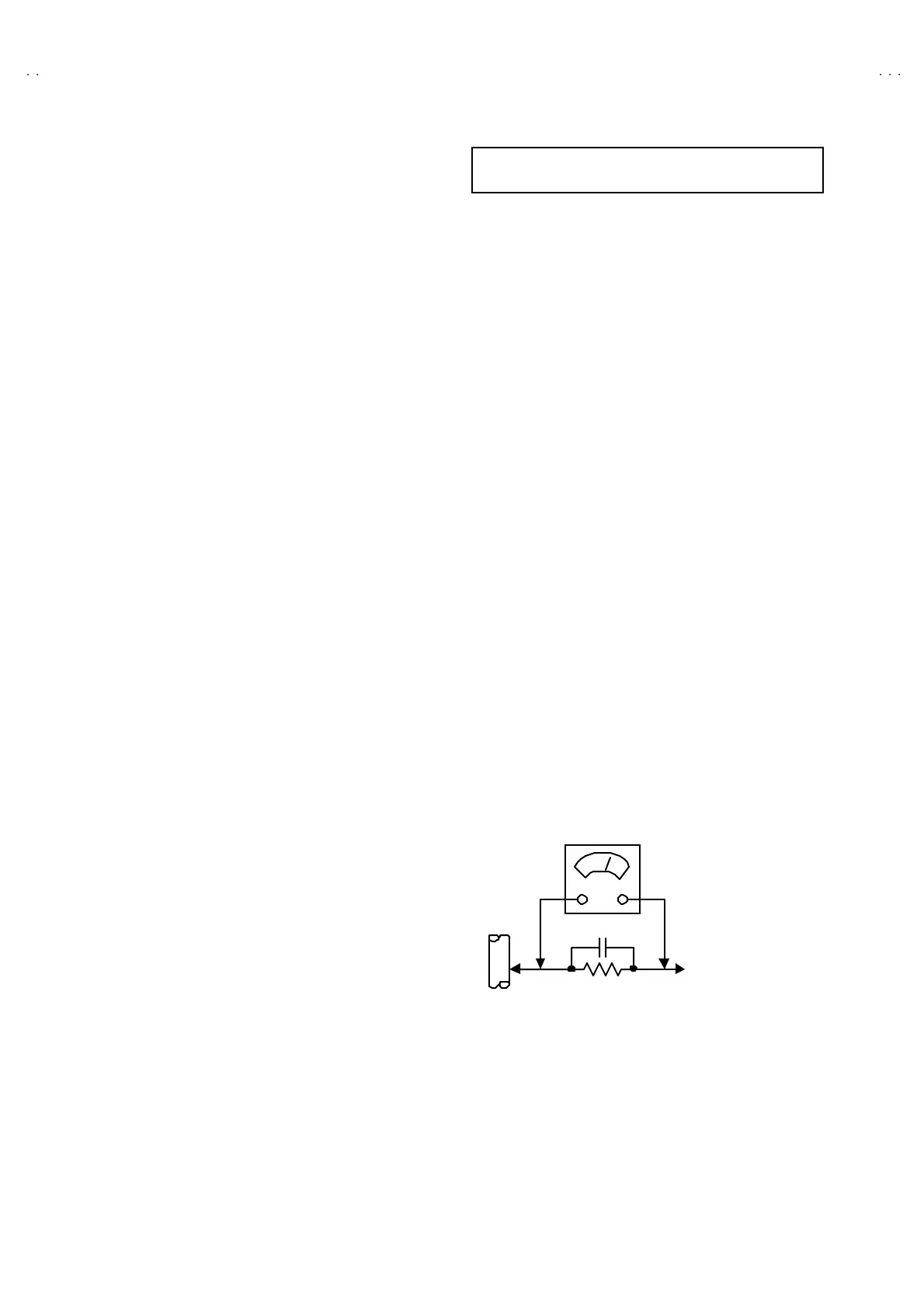
Alte rnate Che ck M ethod
Plug the A C line c ord direct ly in to th e A C ou tlet (d o n ot use a lin e
isolatio n tran sformer during t his che ck.). Use an AC vo lt meter
h aving 1 000 ohms pe r volt or m ore sens it ivity in th e fo llowing
mann er. Con nec t a 1 50 0Ω 10W res ist or para lle le d b y a 0 .1 5µF
AC-type c apa cit or bet we en an expo sed met al pa rt a nd a kno wn
g ood earth gro un d (water pipe , etc.). Meas ure th e A C vo lt age
across th e res ist or with th e AC vo ltmeter . M ove th e r esistor
con nec tion to e ach exp ose d metal par t, p art icularly a ny exp osed
metal p ar t havin g a retu rn pat h to t he ch assis, an d measu re th e
AC voltag e ac ro ss the res ist or. No w, reverse th e plu g in the AC
ou tlet and re pe at eac h mea suremen t. An y volt age me asu re d
must not e xc eed 0.7 5V AC (r.m.s.). This c orresponds to 0.5mA
AC (r.m.s.).
However, in tropical are a, this must n ot exceed 0.3V AC ( r.m. s.).
This corresponds to 0.2mA AC (r.m.s.).
0.15μF AC-T YPE
1500 Ω 10W
GOOD EARTH GROUND
PLACE THIS PROBE
ON E A CH EX PO SE D
ME T AL PA R T
AC VOLTMETER
(HAVING 1000 Ω/V,
OR MORE SENSIT IVITY)
For District of power requirement is 230V~
~~
~
240V AC (Europe, Asia and Oceania)

 Loading...