EasyManua.ls Logo

JVC TM-1500PS

JVC TM-1500PS
40 pages
To Next Page IconTo Next Page
Loading...
CONTENTS
IB
SPECIFICATIONS:
“cc
ecusetuncieaee
tines
sete
newsiews
is
Suaewemcariacdugatuaharte
2
Mi
SAFETY
PRECAUTIONS
........0
2.0000
c
cece
cece
nent
eee
e
eee
ees
iDineat
onc
ens
3
I
OPERATING
INSTHUGTIONS
caucus
ce
oss
vx
care
iis
errs
nea
areal
a
weet
Seances
4
M.
SPECIFIC:
SERVICE
INSTRUCTIONS:
2
f05
ccccea
cds
ey
oven
ste
Mo
eunacds
abi
aeasuncbeny4
8
B-SERVICE
ADUJUSTMENTS...,a.5:ic
nonce
odes
Reinoieeina
ence
ae
od
bases
4
Sioa
aie
He
11
M
PARTSLIST
...........
Rh
aco
elaine
inte
Rca
hana
ihc
alin
Sng
tami
eat
Moa
ahie
19
M
SCHEMATIC
DIAGRAM(APPENDED)
.........0-
20-0
e
cece cece
cece
eect
ee
tenes
O~®
No.50343
COPYRIGHT
©
1989
VICTOR
COMPANY
OF
JAPAN,LTD.
Dec.1989
Question and Answer IconNeed help?

Do you have a question about the JVC TM-1500PS and is the answer not in the manual?

JVC TM-1500PS Specifications

General IconGeneral
Screen Size15 inches
Aspect Ratio4:3
Brightness200 cd/m²
Input ConnectorsBNC
InputRGB

Summary

Specifications

Safety Precautions

Operating Instructions

Controls and Connectors

Front Panel Controls

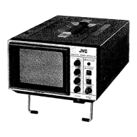
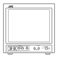
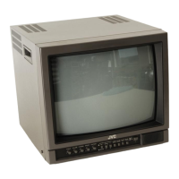
Controls on the front panel for adjusting picture and sound.

Rear Panel Connectors

Input/output connectors located on the rear of the monitor.

Specific Service Instructions

Disassembly Procedure: Top Cover Removal

Steps to remove the top cover of the monitor.

Disassembly Procedure: Rear Cover Removal

Steps to remove the rear cover of the monitor.

Disassembly Procedure: Input PCB Removal

Steps to remove the input printed circuit board.

Disassembly Procedure: Power PCB Removal

Steps to remove the power printed circuit board.

Disassembly Procedure: Main PCB Checking

Steps for checking and accessing the main printed circuit board.

Disassembly Procedure: Front Panel Assembly Removal

Steps to remove the front panel assembly.

Disassembly Procedure: Speaker Removal

Steps to remove the monitor's speakers.

Wire Clamp and Binding Band Precautions

Guidelines for handling wire clamps and binding bands during service.

Service Adjustments

Prior to Starting Adjustment

Preparation steps before performing monitor adjustments.

Adjustment of Main PCB

Procedures for adjusting the Main PCB components.

Adjustment of CRT Socket PCB

Procedures for adjusting the CRT socket PCB.

Adjustment of Purity

Adjusting color purity for accurate display.

Adjustment of Convergence

Adjusting color convergence for sharp image display.

Parts List

Abbreviations of Resistors, Capacitors, and Tolerances

Defines abbreviations for electronic components and their tolerances.

How to Express Parts Numbers

Explains the system for naming standard electronic parts.

Main Parts List

Comprehensive list of primary parts used in the monitor.

CRT Socket PC Board Parts List

List of parts specific to the CRT socket PC board.

Input PC Board Parts List

List of parts specific to the input PC board.

Power PC Board Parts List

List of parts specific to the power PC board.

Module PC Board Parts List

List of parts for module PC boards.

Packing

Packing Parts List

List of components used for product packaging.

Schematic Diagram

Notice and Safety

General notices, safety warnings, and multimeter usage guidelines.

Parts Symbol and Notation

Explanation of component symbols, types, and connection methods.

Schematic Diagram Indication

Details notation for resistors, capacitors, coils, and power supply.

Note for Service on Grounding

Specific instructions regarding grounding differences and short circuits.

Related product manuals