No.51961
TM-H1950CG
8
REMOVING THE SLOT PWB AND SLOT HOLDER
• Remove the top cover, rear panel and terminal bracket.
1. Dett ach th e c onn ector con n ected S LOT PW B and SI GNAL PWB ,
then re move the SLOT PWB with slot hold er.
REMOVING THE CHASSIS BASE
• Remove the top cover, rear panel and terminal bracket.
1. Fall th e unit d own s ide ways as ab le to se e th e b ott om side .
2. Lift th e b ack side of the chass is bas e sligh tly, and s epa ra te it from
bottom c over.
3. Raise the 2 claws positio ned bo tto m of th e ch assis b ase , an d
dettac h the c hass is base from bottom cov er.
4. The n p ull th e ch assis b ase ou t to rearwar d.
REMOVING THE SLOT PWB
•
Remove the SLOT PWB with slot holder from S IGNAL PWB.
1. Rem ove th e 4 screws marked
-
--
-
.
2. The n remove th e S LOT PWB f rom slot ho lder .
REMOVING THE DEFLECTION PWB
•
Remove the top c over.
1. Rem ove th e 2 screws marked
.
..
.
.
2. Dett ach th e con nec tor con nected DE FLECTION PW B a nd MAIN
PWB.
3. Then remove the DEFLECTION PW B.
REMOVING THE BOTTOM COVER
•
Remove the chasssis base.
1. Set the CRT fr ont surf ase do wn war d, an d st and t he b ott om co ver
to facing it t oward you.
At this time, care must be exerc is ed not to damage the front panel
an d CRT sur f ace.
2. Rem ove th e 4 screws marked
/
//
/
an d 2 screws marked
0
00
0
.
3. W hile spre ad in g t he b ott om cove r to t he bo tto m s ide, pu ll it out to
rearward to remove it.
REMOVING THE SPEAKER
•
Remove the top c over.
1. Slight ly sprea d t he c la ws of th e sp eake r ho ld er, a nd pull u p t he
speaker t o remove it.
A METHOD OF ERECTING THE CHASSIS BASE
To check the PW board from back side.
(1) Remove t he chassis b ase an d t he ot her PW board s.
(2) Erect the chassis base vertically so that you can easily c heck the
PW b oard f ro m bac k side .
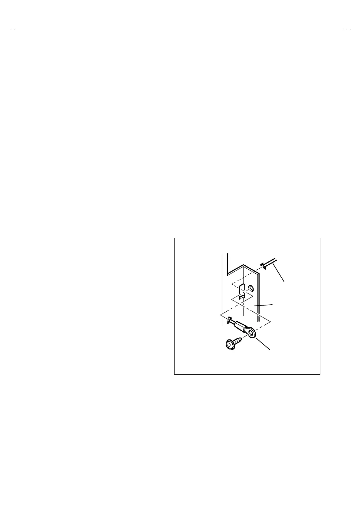
CAUTION
• Before turning on power, make sure that the earth wire properly
connec ted to the terminal bracke t, which is a ttac hed the main
power switch and AC inlet. (Fig.5)
•
An d make sure th at th e CRT ear th wire a nd the oth er connec tors
are prop er ly co nne cted.
•
When er ectin g th e ch assis b ase, be ca reful so t ha t th ere will b e
n o con tac ting with th e oth er PW board .
•
Be caref ul while e recting th e P W bo ard, beca use easily f all d own.
WIRE CLAMPING AND CABLE T YING
1. Be sure to cla mp the wire.
2. Never remo ve the c able tie use d f or tying th e wire s together.
Sh ould it b e in adve rt en tly rem ove d, be sure t o tie th e wir es with a
new cable tie.
EARTH WIRE LUG
EARTH BRACKET
TERMINAL
BRACKET
Fig.5

 Loading...