1-18 (No.MB057)
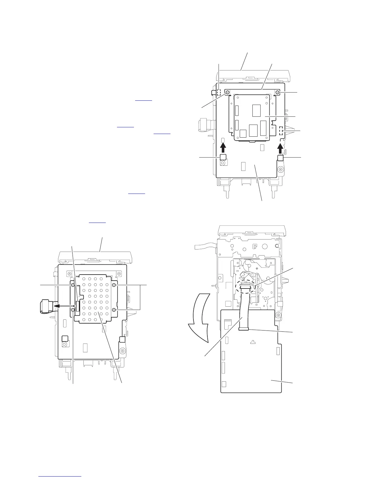
3.1.16 Removing the VCD board / CD servo control board
(See Fig.23~26)
• Prior to performing the following procedure, remove the metal
cover, the rear cover, the rear panel and the VCD mechanism
assembly.
Caution:
Before disconnecting the card wire extending from the CD
pickup, make sure to solder the short-circuit point on the CD
pickup(Fig.25 and 26). If you do not follow this instruction, the
CD pickup may be damaged.
(1) Disconnect the card wire from connector CN101
on the
VCD board on the bottom of the VCD mechanism
assembly.
(2) Remove the four screws B' attaching the board cover.
(3) Disconnect the wire from connector CN801
on the CD ser-
vo control board and the card wire from connector CN606
respectively.
(4) Remove the two screws D' attaching the CD servo control
board and the board bracket.
(5) Move the CD servo control board in the direction of the
arrow to release two joints m.
(6) Turn and move the CD servo control board in the direction
of the arrow.
(7) Solder the short-circuit point on the CD pickup.
(8) Disconnect the card wire from connector CN601
on the CD
servo control board.
Caution:
When reassembling, unsolder the short-circuit point after
connecting the card wire to CN601
on the CD board.
Fig.23
Fig.24
Fig.25
VCD mechanism assembly
Board cover
CN101
B' B'
B'
VCD mechanism assembly
Board bracket
CD servo control board
VCD board
CN801
CN606
m m
D'
D'
CD servo
control board
CN601
Card wire
Short round
 Loading...