1-12
UX-L40R/UX-L30R
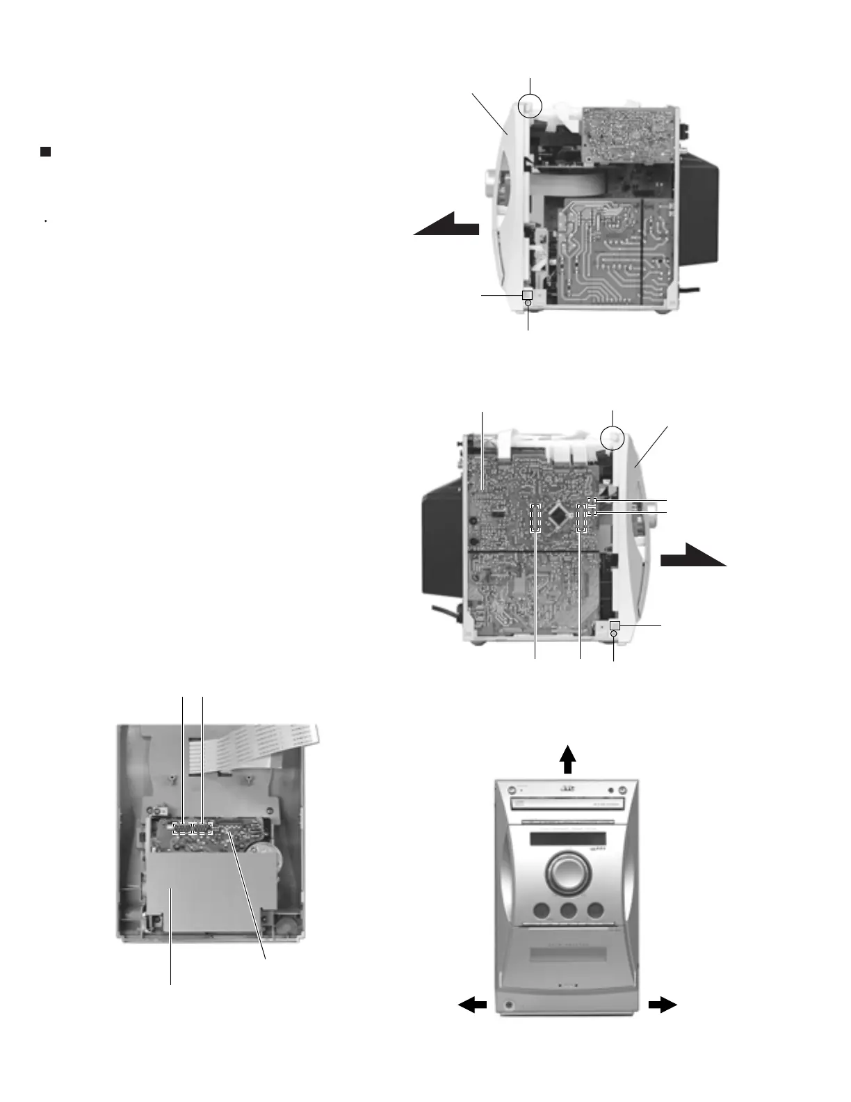
Remove the metal cover.
Remove the screw K on each side. Pull the joint h
on both sides and lift the front panel assembly to
release the joint g.
Disconnect connector CN931, CN935, CN933 and
CN934 on the main board.
Disconnect the card wire from connector CN33 and
CN34 on the cassette mechanism board.
1.
2.
3.
Removing the Front panel assembly
(See Fig.13 to 16)
Fig.13
Fig.14
Fig.15Fig.16
Main board
Front panel
assembly
Front panel
assembly
CN935 CN931
CN933
CN934
CN34 CN33
Cassette mechanism
board
Cassette mechanism
assembly
K
K
h
hh
g
g
h
g
 Loading...