1-21
UX-L40R/UX-L30R
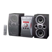
Remove the cassette mechanism assembly.
After turning over th cassette mechanism assembly,
remove the three screws A retaining the head
amplifier & mechanism control board.
Disconnect the connector CN32 on the board
including the connector CN1 on the reel pulse P.C.
board.
When necessary, remove the 4 pin parallel wire
soldered to the main motor.
1.
2.
3.
4.
Removing the head amplifier & mechanism
control board (See Fig. 4)
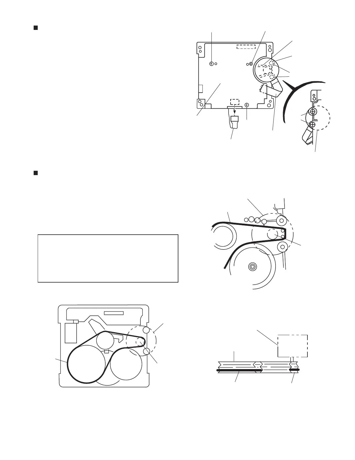
Remove the two screws B retaining the main motor
assembly (See Fig. 4 and 4a).
While raising the main motor, remove the capstan
belt from the motor pulley (See Fig. 4a).
1.
2.
Removing the main motor assembly
(See Fig.4 ~ 6)
Be sure to handle the capstan belt so
carefully that this belt will not be stained
by grease and other foreign matter.
Moreover, this belt should be hanged
while referring to the capstan belt
hanging method in Fig. 5 and 6.
CAUTION:
Belt
Main motor
assembly
Head amplifier &
mechanism control
board
Flexible board
4pin parallel wire
Main motor
assembly
Fig. 4
Fig. 4a
Main motor
assembly
Capstan belt
Motor
pulley
Fig. 6
Main motor
assembly
Flywheel
Motor pulley
Capstan belt
Fig. 5
Mechanism motor
assembly
Motor
pulley
Capstan
belt
CN32
CN31
A
A
A
B
B
 Loading...