UX-M3R
1-13
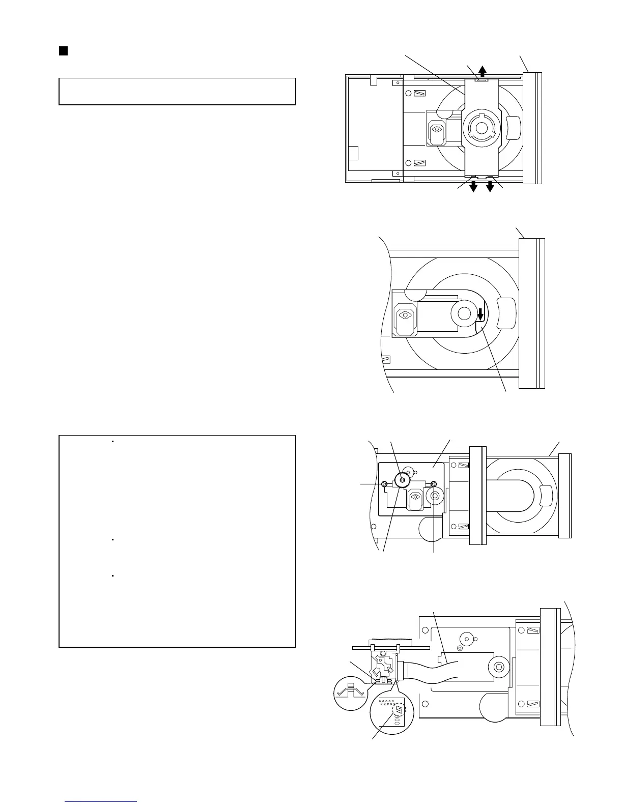
Fig.30
Fig.31
Fig.32
Fig.33
Clamper assembly
Front panel assembly
Claw p
Claw g
Y
Y
CD pickup assembly
Front panel assembly
Claw g
r section
TraySlit washer
Feed middle gear
Card wire
Sliding spring
Short land part n
Replacing the CD pickup unit
(See Figs. 30 to 33.)
1.
2.
3.
4.
5.
6.
7.
8.
9.
Remove the left and right side panels (see Figs. 3
to 6).
Remove the top cover (see Figs. 7 and 8).
On the top of the main body, open up the claws p
and q on the left and right of the clamper assembly
in the direction of the arrows and lift the assembly
to remove it.
On the top of the main body, push section r on the
elevator of the CD mechanism assembly and lower
the CD pickup assembly.
Pull out the tray.
Remove the slit washer retaining the feed middle
gear, and take out the feed middle gear.
Remove the two screws Y retaining the shaft.
Turn the CD pickup unit upside down and apply
solder to the short land part n.
Disconnect the card wire from the CD pickup unit
and replace the unit.
[Note] Use the following procedure to replace
only the CD pickup unit.
[Caution] Be sure to solder the short land
part n on the CD pickup unit before
disconnecting the card wire from the
CD pickup unit (see Fig. 33).
If the card wire is disconnected
without attaching solder, the CD
pickup may be destroyed by static
electricity.
In the assembly, be sure to remove
solder from the short land part n
after connecting the card wire.
[Note] Removing the CD pickup unit
involves the removal of the sliding
spring. In the assembly, be sure to
attach the spring in the correct
orientation before attaching the CD
pickup unit (see Fig. 33).
 Loading...