UX-M3R
1-20
2.Pin function
Pin
No.
Symbol I/O Function
1
2
3
4
5
6
7
8
9
10
11
12
13
14
15
16
17
18
19
20
21
22
23
24
25
26
27
VSS
XOUT
XIN
RESERT
XTOUT
XTIN
TEST
SHIFT FREQ.
REMOTE
MUTE
PLAY MUTE
REC MUTE
PLAY/REC
(SCK2)
(SI2)
(SO2)
REC SW (RCS)/(WAIT)
REC SW (FWD)
SOL.
MODE SW
VOL STB
POWER
B-HALF SW
JOG-B/VOL DATA
JOG-A/VOL CLK
RDS CLK
V-MOTOR
GND (0V)
Resonator connecting pins for high clock(4-8MHz).
For inputting external clock, XIN is used and XOUT is
opened.
Reset signal input
or watchdog timer output/address-trap-reset output
Resonator connecting pins for slow clock(32.768kHz)
or general purpose I/O.
Test pin for out-going test. Always fixed to low.
Shift the crystal oscillation frequency to reduce tuner
noise.
Remote control signal input
Audio mute output
Muting output during play
Muting output during recording
Play or recording output, low for recording.
Not connected
Not connected
Not connected
Deck reverse record protection input. Low means can
record on reverse side.
Deck forward record protection input. Low means can
record on forward side.
Solenoid output for deck B.
Mode switch input of deck B. Low means the head is
up.
TC9422F volume STB output
Power output control
Half switch input of deck B. Low means deck B have
tape.
Jog dial input and TC9422F volume data output
Jog dial input and TC9422F volume clock output
BU1923F(RDS demodulator) interface CLK input
Motor output
-
O
I
I/O
O
I
I
O
I
O
O
O
O
-
-
-
I
I
O
I
O
O
I
I/O
I/O
I
O
Pin
No.
Symbol I/O Function
28
29
30
31
32
33
34
35
36
37
38
39
40
41
42
43
44
45
46
47
48
49
50
51
52 91
92 95
96
97
98
99
100
B-PHOTO OUTPUT
CD-RW
RES
CCE
BUCK
BUS0
BUS1
BUS2
BUS3
TRAY IN (SLOUT)
TRAY OUT (SLIN)
SLT
CLT (SLEND)
NC
RDS DATA
STEREO
PWR DET
AD K3
AD K2
AD K1
VAREF
(BOOT)
VSS
VDD
SEG39 0
COM3 0
VLC
PLL DATA
PLL CLK
PLL PRD
VDD
Reel pulse input of deck B. Have pulse input means
the tape is rotating.
CD-RW control output
CD servo reset output
Servo DSP chip enable output
Servo DSP clock output
Servo DSP command and data I/O
Servo DSP command and data I/O
Servo DSP command and data I/O
Servo DSP command and data I/O
Tray open/close outputs for current sensor drawer type
mechanism.
CD pick up position input: L if pick up is in inner side.
Current sensor input
Not connected
BU1923F(RDS demodulator) interface data input
Stereo input pin for tuner stereo indication
Power down detection
Panel key analog input
Panel key analog input
Panel key analog input
Analog reference voltage input
Control input for writing MCU program area via ICU
interface.
GND (0V)
VDD (+5V)
LCD segment outputs
LCD common outputs
LCD drive power supply
TC9257P (PLL) interface
TC9257P (PLL) interface
TC9257P (PLL) interface
VDD (+5V)
I
O
O
O
O
I/O
I/O
I/O
I/O
O
O
I
I
-
I
I
I
I
I
I
-
I
-
-
O
O
-
I/O
O
O
-
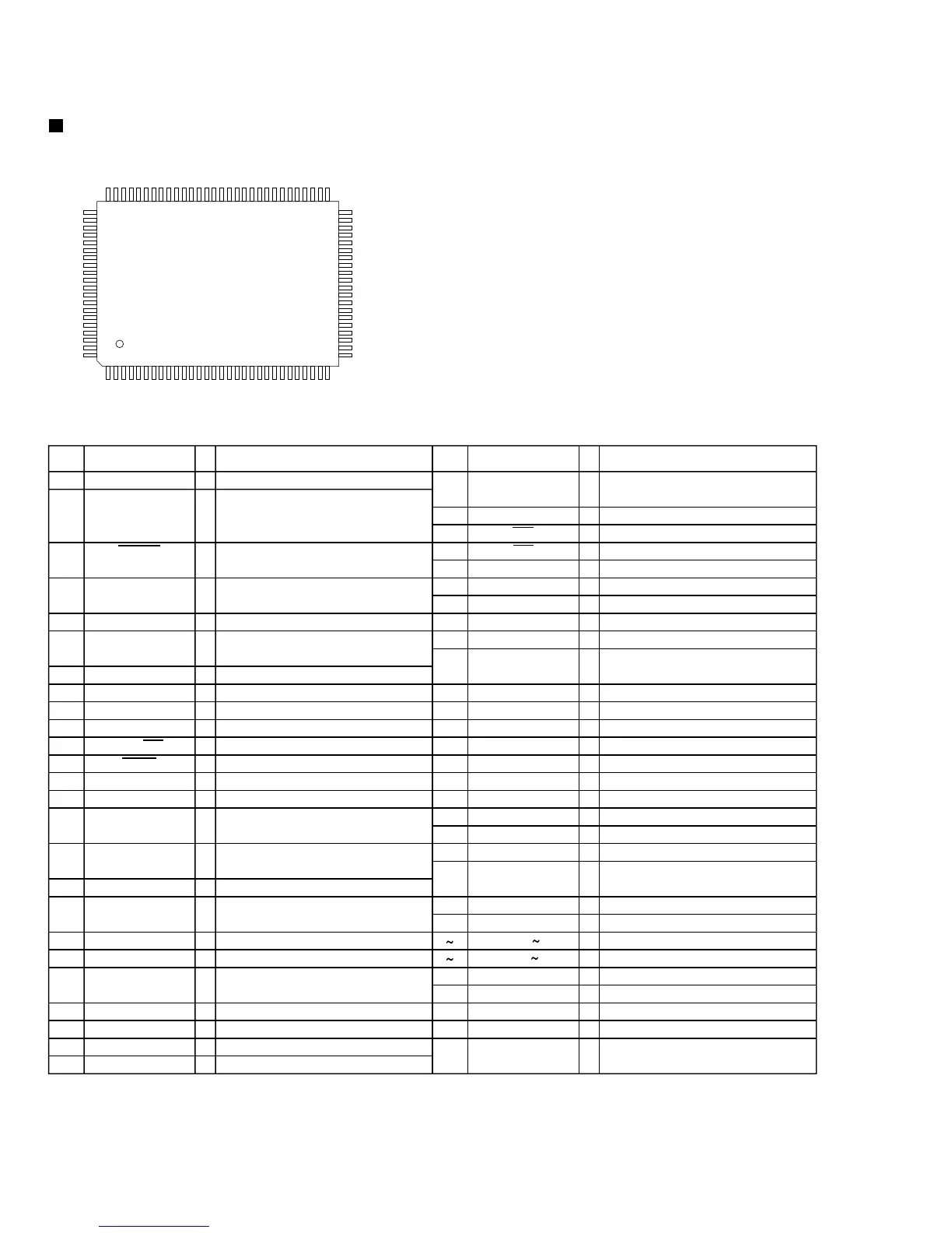
TMP87EP26F (IC601) : MCU
1. Terminal layout
Description of major ICs
81
82
83
84
85
86
87
88
89
90
91
92
93
94
95
96
97
98
99
100
(Top view)
1
2
3
4
5
6
7
8
9
10
11
12
13
14
15
16
17
18
19
20
21
22
23
24
25
26
27
28
29
30
50
49
48
47
46
45
44
43
42
41
40
39
38
37
36
35
34
33
32
31
80
79
78
77
76
75
74
73
72
71
70
69
68
67
66
65
64
63
62
61
60
59
58
57
56
55
54
53
52
51
 Loading...