UX-M3R
1-7
D
D
H
Fig.8
Fig.11Fig.10
Fig.9
Fig.7
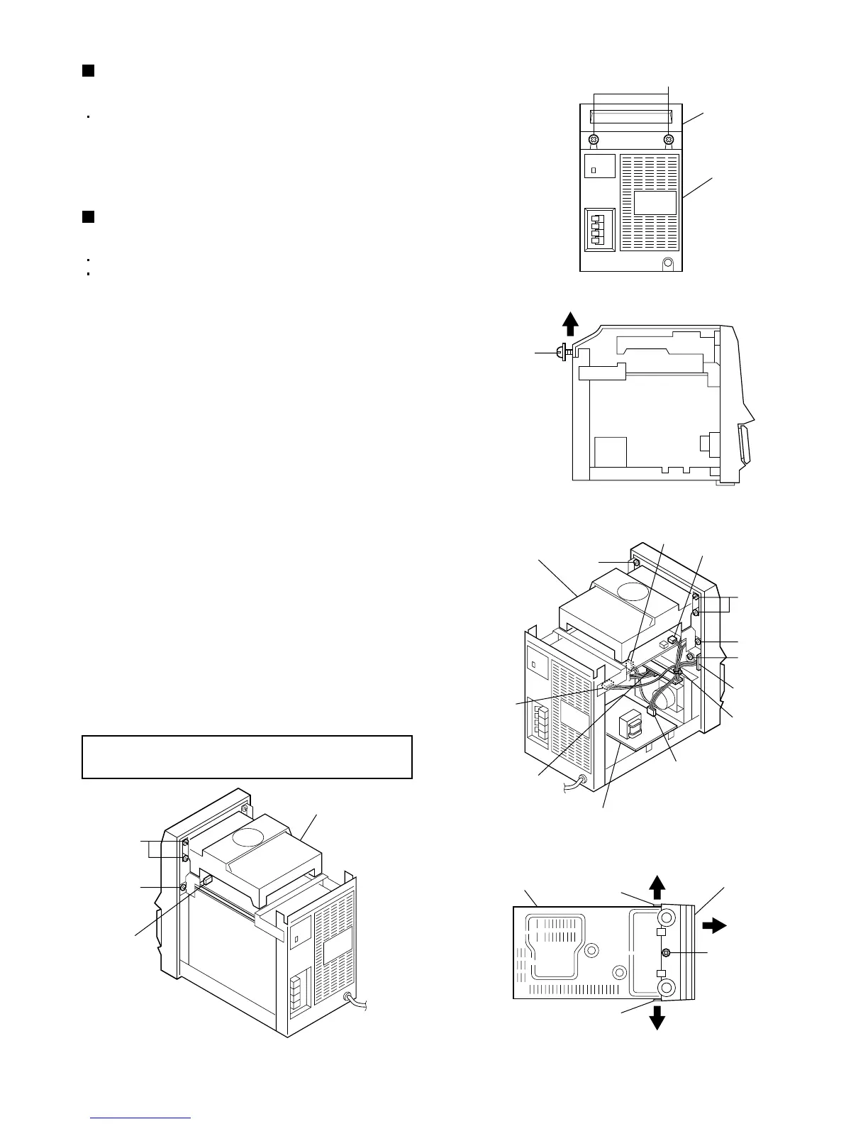
Lift the rear
part to remove.
Top cover
(To be loosened)
Rear panel
1
2
1
Ear phone
board
Connector on the
cassette switch
board
Power board
Tie band
CN902
CN402
CN608
CD mechanism
assembly
Front panel assembly
Hook d
Hook d
F
F
F
G
G
E
CD mechanism
assembly
CN607
Chassis
CN201
Removing the top cover
(See Figs. 7 and 8.)
1.
2.
From the back side of the main body, loosen the
two screws D retaining the top cover.
Lift the rear part of the top cover to remove it.
Removing the front panel assembly
(See Figs. 9 to 11.)
1.
2.
3.
4.
5.
6.
7.
8.
9.
Remove the tie band bundling the wires.
Disconnect the wire from the connector CN902 on
the power board.
Disconnect the wire from the connector on the
cassette switch board.
Remove the screw E retaining the bracket on the
ear phone board.
Disconnect the wires from the two connectors
CN201 and CN402 on the main board.
Disconnect the wires from the two connectors
CN607 and CN608 on the CD & MCU board.
Remove the four screws F and the two screws G
retaining the bracket of the CD mechanism
assembly from the left and right.
Remove the screw H retaining the front panel
assembly from the bottom side of the main body.
While opening the hooks d to the left and right of
the lower part of the front panel assembly (in the
direction of arrows 1), slide the front panel
assembly toward the front (in the direction of arrow
2).
Remove the left and right side panels.
Remove the left and right side panels.
Remove the top cover.
[Note] After assembly, apply a locking agent to
the screws F and G.
 Loading...