1-10
UX-P3
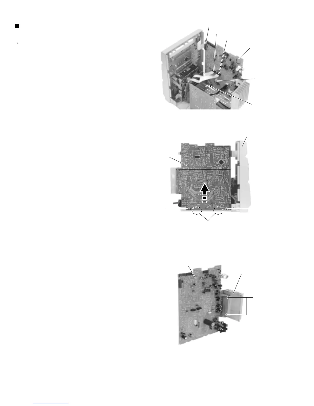
Prior to performing the following procedure, remove
the metal cover, the rear cover, the CD mechanism
assembly and the rear panel.
Disconnect the card wire from connector CN900,
CN901 and CN931 on the main board.
Disconnect the wire from CN906 and FW903
respectively.
Disconnect the wire from W950 on the underside of
the main board.
Remove the two screws I attaching the main board
to the chassis on the left side ofthe body and
disengage the two joints c.
Remove the two screws J attaching the heat sink to
the main board.
1.
2.
3.
4.
Removing the main board / heat sink
(See Fig.13 to 15)
Fig.14
Fig.13
Fig.15
Front panel assembly
Main board
I
I
Joints c
Heat sink
Main board
CN931
CN901
CN900
CN906
FW906
Main board
J
 Loading...


