1-12
UX-P3
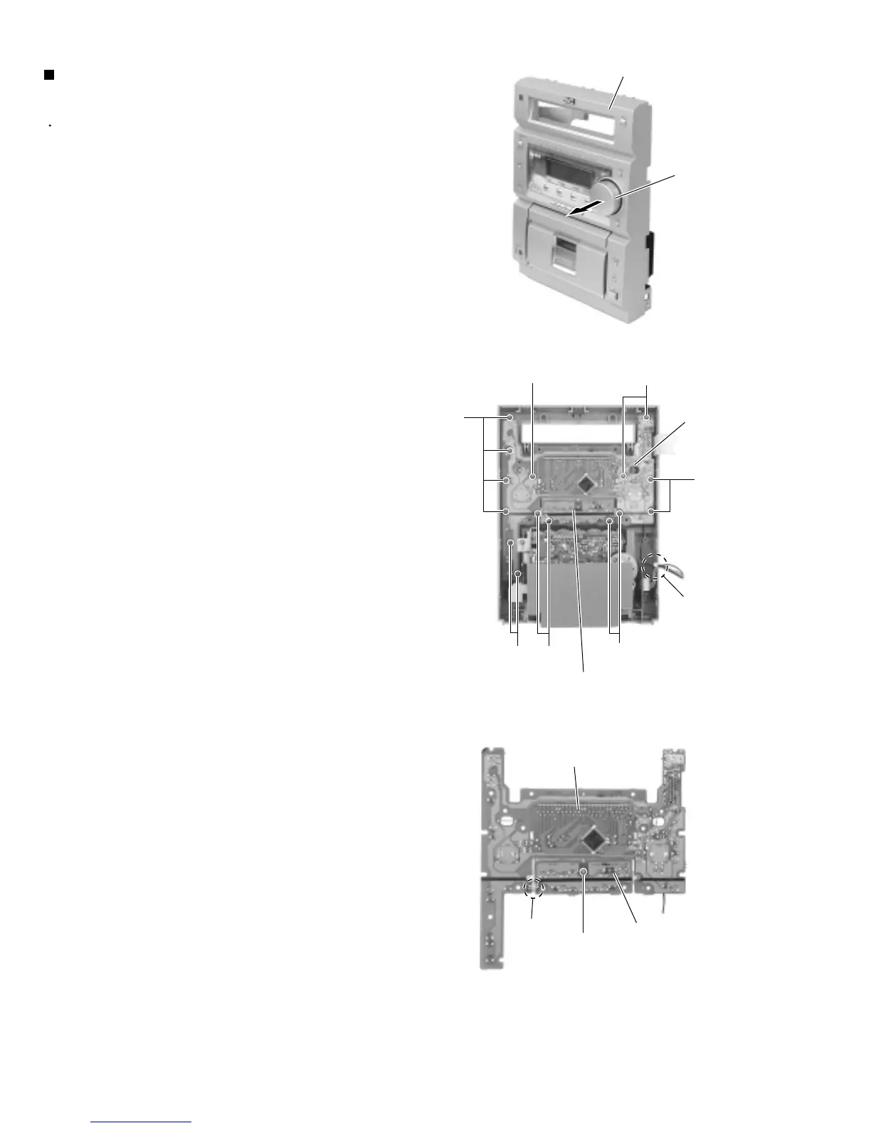
Prior to performing the following procedure, remove
the front panel assembly.
Pull out the VOLUME knob on the front panel.
Remove the fifteen screws M attaching the display
board and the switch board on the back ofthe front
panel. Remove the display board with the switch
board.
Remove the screw N attaching the switch board to
the LCD holder.
If necessary, unsolder the wire extending from
connector FW931 on the display board and FW931
on the switch board.
If necessary, remove the band bundling the wires
extending from the headphone board and the display
board.
1.
2.
3.
4.
5.
Removing the display board / switch
board (See Fig.20 to 22)
Front panel assembly
VOLUME knob
Display board
Switch board
M
M
M
M
M
M
M
Band
Switch board
Display board
FW931
N
Fig.20
Fig.21
Fig.22
 Loading...


