1-36
UX-P3
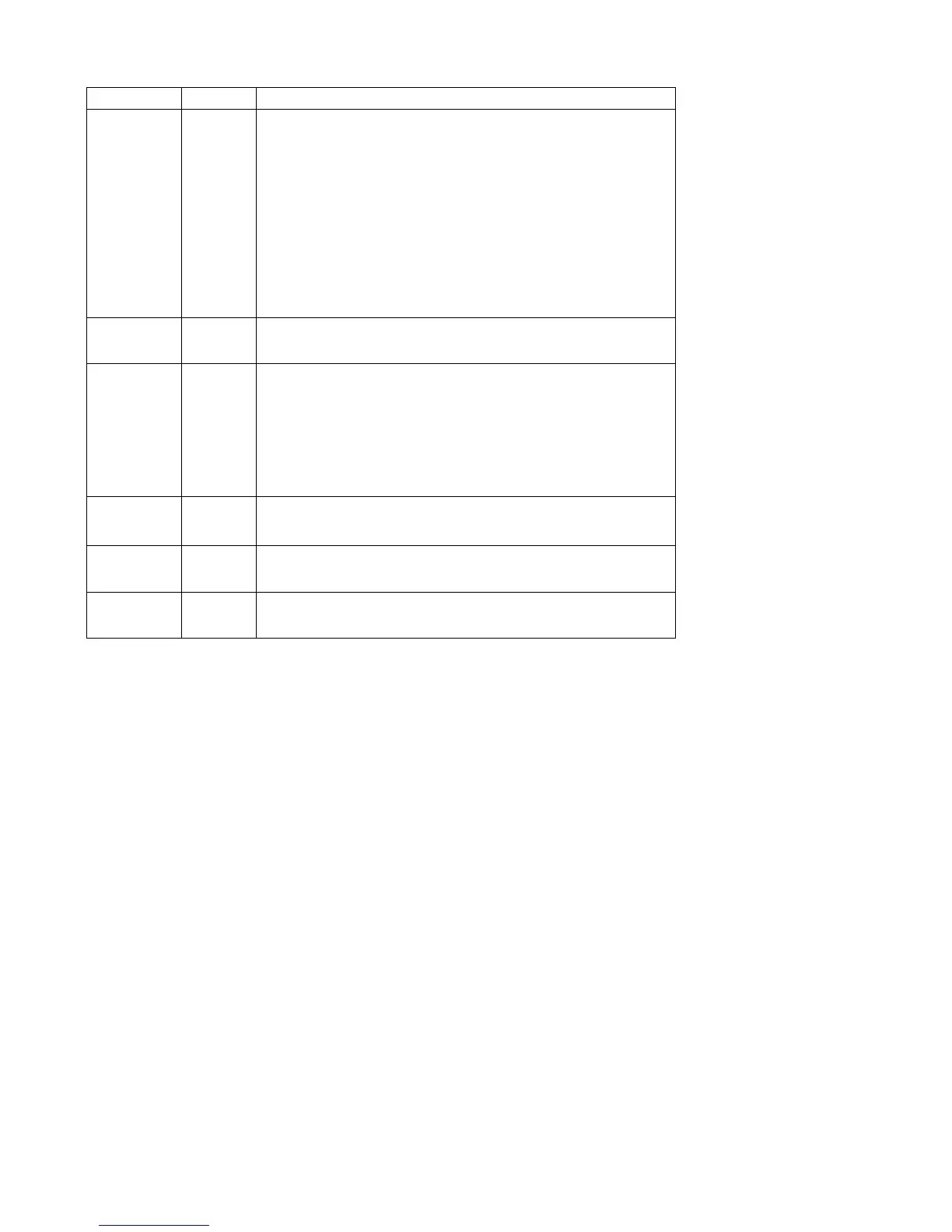
3. Descriptions
Pin name Pin No.
Descriptions
L1
L2
L3
L4
L5
R1
R2
R3
R4
R5
18
17
16
15
14
20
21
22
23
24
Input signal pin
LSEL0
RSEL0
13
25
Input selector output pin.
LBASS1
LBASS2
RBASS1
RBASS2
LSB
RSB
10
9
28
29
8
30
Capacitor and resistor connection pins comprising filters for
bass and super-bass band.
LOUT
ROUT
7
31
ATT + equalizer output pin/capacitor connection pin
comprising filter for super-bass
LVRIN
RVRIN
12
26
Volume input pin
LTRE
RTRE
11
27
Capacitor connection pin comprising treble band filter.
 Loading...


